
IEC Standard for Differential Protection
Differential protection is one of the fastest and most selective protection methods used in modern power systems. It compares the current entering and leaving a protected zone and trips the circuit breaker when the difference indicates an internal fault. Understanding the IEC Standard for Differential Protection is important when selecting protection functions, CTs, relays, wiring arrangements, and operating characteristics.
IEC standards provide the framework for designing, testing, and applying protection equipment. However, there is not one single IEC document that covers every aspect of differential protection. Different standards address protection relays, instrument transformers, power transformers, switchgear, and functional requirements.
| Key Item | Typical IEC Reference | Purpose |
|---|---|---|
| Protection relay requirements | IEC 60255 series | Requirements and testing of measuring relays and protection equipment |
| Transformer differential protection | IEC 60076 series | Power transformer design and protection considerations |
| Instrument transformers | IEC 61869 series | CT and VT requirements |
| High-voltage switchgear | IEC 62271 series | Switchgear and circuit-breaker requirements |
| Protection system testing | IEC 60255 series | Relay performance and verification |
| Differential protection principle | Application-dependent | Detects internal faults within a defined zone |
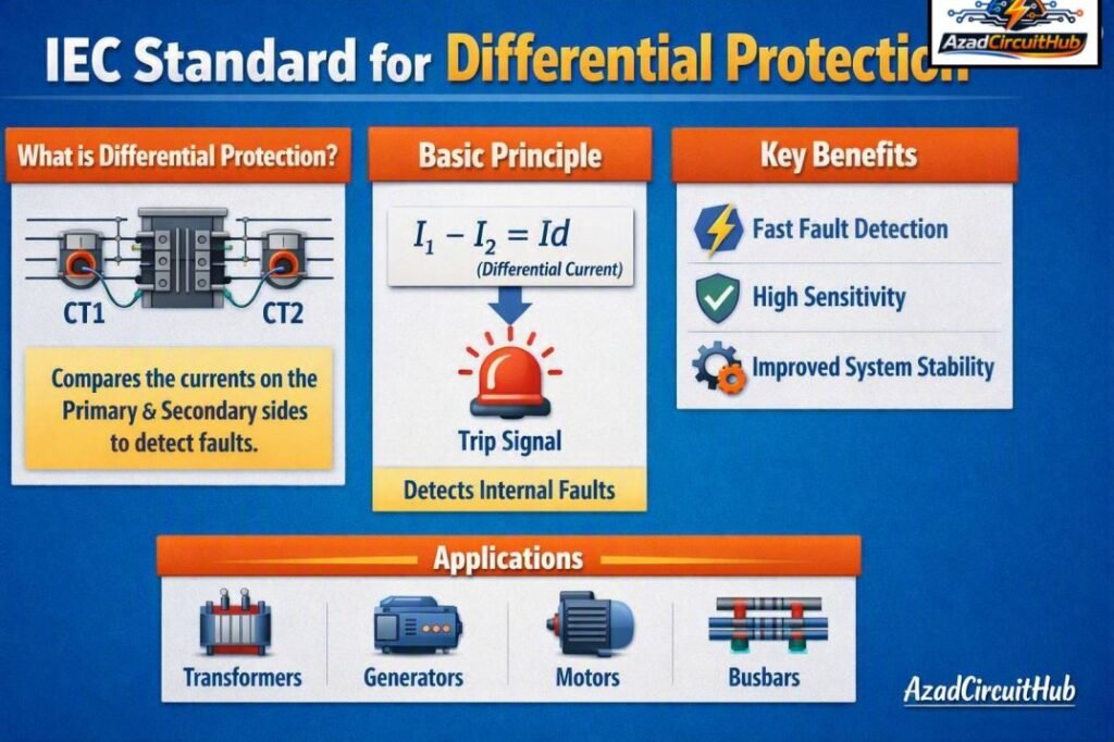
Table of Contents
Table of Contents
What Is Differential Protection?
Differential protection operates on the principle that the current entering a protected section should be approximately equal to the current leaving it during normal operation and external faults.
For a simplified protected zone:
Differential Current = |I₁ − I₂|
When the differential current exceeds the relay’s operating threshold, the protection system can issue a trip command.
For AC systems, the relay must also consider CT ratio, CT polarity, phase displacement, vector group, wiring, and measurement errors. These factors are especially important for transformer differential protection.
| Operating Condition | Expected Differential Current | Relay Response |
|---|---|---|
| Normal load | Very low | No trip |
| External fault | Ideally low | Restraint |
| CT saturation | May increase | Stabilization required |
| Internal fault | High | Trip |
| Transformer energization | Temporary high current | Inrush restraint/blocking |
The protected zone may include a transformer, generator, motor, busbar, cable, or transmission line. The CTs are normally installed at the boundaries of this zone.
IEC Standard for Differential Protection Relays
The IEC 60255 family is particularly important for protection relays. IEC 60255 covers measuring relays and protection equipment, including requirements related to performance, insulation, electromagnetic compatibility, environmental conditions, and testing.
For engineers working with differential relays, IEC 60255 is more useful when combined with the relevant equipment standard and the manufacturer’s application documentation.
A protection relay should not be selected only by its differential function. Its accuracy, operating characteristics, CT input requirements, communication interfaces, disturbance recording, and environmental ratings also need consideration.
| Relay Parameter | Why It Matters |
|---|---|
| Differential pickup | Determines minimum operating current |
| Bias/restraint characteristic | Improves security during external faults |
| CT input rating | Must match the instrument transformer circuit |
| Operating time | Determines fault-clearing speed |
| Harmonic restraint | Helps prevent unwanted transformer trips |
| Event recording | Supports fault investigation |
| Communication | Enables modern substation protection schemes |
IEC 60255 and Differential Protection
IEC 60255 is a key reference when evaluating the performance of numerical protection relays. Modern differential relays use digital measurement and algorithms to calculate differential and restraint currents.
The standard should be viewed as part of a larger protection design rather than as a standalone relay-setting guide.
For example, a transformer differential protection scheme may need to consider:
- CT accuracy and saturation characteristics
- CT ratio matching
- Transformer vector group
- Phase compensation
- Zero-sequence current
- Transformer tap position
- Magnetizing inrush
- Overexcitation
- Internal and external fault levels
- Relay operating and restraint characteristics
Correct application of these factors helps achieve both dependability and security.
Transformer Differential Protection Standards
Transformer differential protection is commonly associated with the IEC 60076 family, which covers power transformers. IEC 60076 addresses transformer construction, ratings, testing, insulation, temperature rise, and other technical requirements.
The actual protection scheme depends on the transformer rating, voltage level, grounding arrangement, winding configuration, and system fault characteristics.
A transformer differential relay compares the currents on different transformer sides after compensating for ratio and phase-angle differences.
| Transformer Factor | Effect on Differential Protection |
|---|---|
| Transformer ratio | Determines CT ratio and compensation |
| Vector group | Creates phase displacement |
| Tap changer | Changes effective transformation ratio |
| Winding connection | Affects current and zero-sequence paths |
| Neutral grounding | Influences earth-fault protection |
| Inrush current | Can resemble an internal fault |
| CT saturation | Can produce false differential current |
For larger transformers, differential protection is often combined with restricted earth fault, overcurrent, thermal, Buchholz, and other protection functions.
CT Requirements for Differential Protection
Current transformers are critical to differential protection because the relay depends on accurate current measurements.
IEC 61869 is the modern IEC family covering instrument transformers. When selecting CTs for a differential scheme, engineers should review the CT ratio, accuracy class, burden, knee-point voltage where applicable, saturation behavior, and secondary wiring.
CT polarity is equally important. Reversed CT polarity can make healthy load current appear as differential current and may cause an unwanted trip.
A well-designed CT circuit should therefore be checked during commissioning rather than relying only on wiring drawings.
For detailed relay-current calculations, use a Differential Protection Relay Setting Calculator to estimate differential and restraint quantities before finalizing protection settings.
Differential Protection Operating Characteristics
Numerical differential relays commonly use a percentage-biased or restrained characteristic. The relay compares differential current with a restraint quantity.
A simplified representation is:
Idiff = |I₁ − I₂|
Irestraint ≈ (|I₁| + |I₂|) / 2
The actual equation varies by relay manufacturer and protection algorithm.
The bias characteristic allows the relay to remain stable during high through-fault currents where CT saturation can create measurement errors.
| Protection Characteristic | Main Advantage |
|---|---|
| Low-set differential | Detects lower internal faults |
| High-set differential | Provides fast operation for severe faults |
| Percentage restraint | Improves stability |
| Dual-slope characteristic | Handles different fault-current ranges |
| Harmonic restraint | Helps prevent inrush-related trips |
Before selecting a pickup or bias setting, check the calculation with a Differential Protection Relay Setting Calculator and compare the result with the relay manufacturer’s setting philosophy.
CT Saturation and Stability
CT saturation is one of the main challenges in differential protection. During a heavy external fault, one CT may saturate before another. This creates unequal secondary currents even though the primary currents should theoretically balance.
The resulting spill current can be interpreted as an internal fault.
Protection engineers therefore consider CT performance, system fault current, secondary burden, cable resistance, and relay stabilization when designing the scheme.
A percentage-restraint characteristic provides additional security against these unwanted operations.
Transformer Inrush and Harmonic Restraint
Transformer energization can produce a large magnetizing inrush current. Although this current may be much higher than normal load current, it is not necessarily evidence of an internal winding fault.
Modern transformer differential relays can use harmonic analysis and other algorithms to distinguish inrush from internal faults.
| Condition | Typical Protection Concern | Common Solution |
|---|---|---|
| Energization | Magnetizing inrush | Harmonic restraint/blocking |
| Overexcitation | Excessive flux | V/Hz protection |
| External fault | CT saturation | Percentage restraint |
| Internal winding fault | High differential current | Fast differential trip |
| Earth fault | Zero-sequence current | REF/earth-fault protection |
Testing and Commissioning
Testing is essential before placing a differential protection system into service. Relay settings should be verified against the approved protection study, while CT circuits should be checked for polarity, continuity, ratio, and correct phase identification.
A typical commissioning sequence includes:
- Verify relay model and approved settings.
- Confirm CT ratios and wiring.
- Perform CT polarity checks.
- Verify phase sequence.
- Check secondary circuit continuity.
- Inject currents into the relay.
- Confirm differential and restraint measurements.
- Test trip outputs and breaker interfaces.
- Verify alarms and communication.
- Record test results for future maintenance.
Secondary injection testing is particularly useful because it allows engineers to verify relay operating points without applying primary fault current.
Common Mistakes in Differential Protection
Several errors can reduce the reliability of a differential protection scheme.
| Mistake | Possible Result |
|---|---|
| Incorrect CT polarity | False differential current |
| Wrong CT ratio | Measurement mismatch |
| Incorrect vector-group compensation | Phase-current imbalance |
| Excessive CT burden | Increased saturation risk |
| Poor grounding | Unsafe or unstable circuits |
| Incorrect relay slope | Security or sensitivity problems |
| Ignoring inrush | Transformer nuisance tripping |
| Incorrect test configuration | Commissioning failures |
The IEC Standard for Differential Protection should therefore be applied together with the equipment manufacturer’s instructions, approved protection studies, and applicable national electrical requirements.
How to Select Differential Protection Settings
Protection settings should be based on the protected equipment and the complete power-system study rather than copied from another installation.
Important inputs include rated current, maximum load, minimum and maximum fault current, CT ratios, CT characteristics, transformer impedance, grounding method, and relay operating characteristics.
The basic design objective is to provide enough sensitivity for internal faults while maintaining stability during external faults and abnormal operating conditions.
For a practical starting point when checking these values, use our Differential Protection Relay Setting Calculator to work through the key differential and restraint calculations.
Frequently Asked Questions
1. What IEC standard is used for differential protection?
IEC 60255 is a major standard family for measuring relays and protection equipment. Equipment-specific standards, such as IEC 60076 for transformers and IEC 61869 for instrument transformers, are also relevant to a complete differential protection system.
2. Does IEC 60255 define all differential relay settings?
No. IEC 60255 establishes requirements and performance aspects for protection equipment, but the actual differential pickup, bias slope, harmonic restraint, and other settings depend on the protected equipment, system study, relay manufacturer, and application.
3. Which IEC standard covers CTs used for differential protection?
IEC 61869 covers instrument transformers, including current transformers. CT selection for differential protection should consider ratio, accuracy, burden, saturation performance, and the requirements of the protection scheme.
4. Why is CT polarity important in differential protection?
Correct CT polarity ensures that currents entering and leaving the protected zone are compared in the correct direction. Incorrect polarity can create artificial differential current and potentially cause an unwanted relay operation.
5. Can differential protection operate during an external fault?
A properly designed differential protection scheme should remain stable for external faults. CT saturation can create apparent differential current, which is why biased characteristics, suitable CTs, correct wiring, and proper relay settings are important.
Final Thoughts
Understanding the IEC Standard for Differential Protection requires more than knowing a single IEC number. Reliable protection combines IEC 60255 requirements with the relevant transformer, instrument-transformer, switchgear, and system standards.
Correct CT selection, polarity, phase compensation, restraint characteristics, inrush detection, and commissioning tests all contribute to dependable operation. The final relay settings should always be verified against the protection study and the manufacturer’s technical documentation before commissioning.
Get new guides in your feed. Follow Electrical Insights on LinkedIn for new electrical standards guides, calculators and design tips from Azad Circuit Hub.
#IECStandardForDifferentialProtection, #DifferentialProtection, #IECStandards, #ProtectionRelay, #PowerSystemProtection, #TransformerProtection, #ElectricalProtection, #IEC60255, #ElectricalEngineering, #RelayProtection
