
How to Use a Thermal Camera for Electrical Faults
Electrical problems do not always show visible signs. A loose connection, overloaded conductor, damaged breaker, or failing motor can heat up long before it causes smoke or equipment failure. This is where thermal imaging becomes a valuable diagnostic method. Learning How to Use a Thermal Camera correctly can help electricians find abnormal heat patterns without shutting down equipment unnecessarily.
A thermal camera detects infrared radiation and converts temperature differences into a visual image. Instead of looking only at voltage, current, or resistance, you can see where electrical components are producing excessive heat. This makes infrared inspection useful for electrical panels, circuit breakers, busbars, disconnects, transformers, motors, cable terminations, and other energized equipment.
Thermal Camera Features for Electrical Troubleshooting
| Feature | FLIR Systems E4 | FLIR E5 |
|---|---|---|
| Thermal resolution | 80 × 60 pixels | 120 × 90 pixels |
| Thermal sensitivity | Approximately 0.15°C | Approximately 0.10°C |
| Temperature range | -20°C to 250°C | -20°C to 250°C |
| Image enhancement | FLIR MSX | FLIR MSX |
| Thermal imaging | Yes | Yes |
| Visible camera | Yes | Yes |
| Typical application | Electrical and maintenance inspections | Electrical, HVAC and maintenance inspections |
| Best suited for | Basic professional thermal surveys | More detailed thermal inspection |
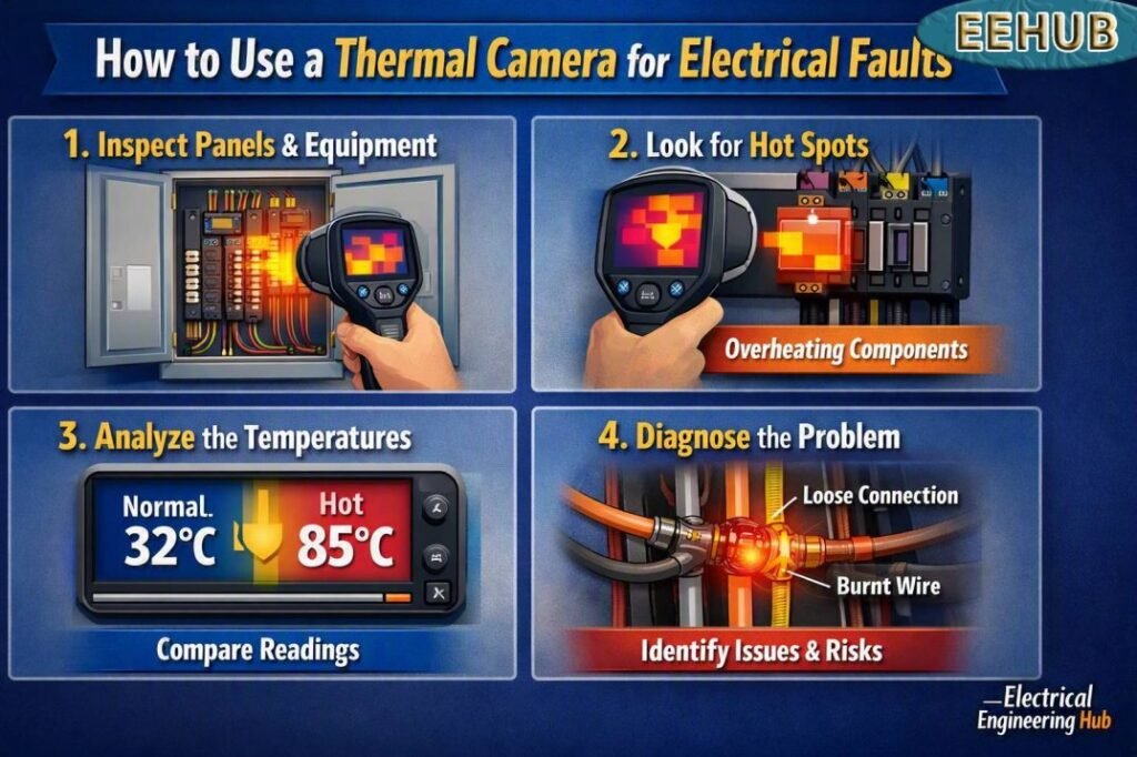
Table of Contents
Table of Contents
What Does a Thermal Camera Detect?
A thermal imaging camera does not directly identify an electrical fault. Instead, it shows temperature differences that can indicate a developing problem.
For example, a loose cable lug may have higher electrical resistance at the connection point. When current flows through that resistance, heat is produced. The thermal camera can reveal the hot connection while the surrounding conductors remain relatively cool.
Common problems that thermal imaging can help identify include:
- Loose electrical connections
- Overloaded circuits
- Unbalanced electrical loads
- Damaged circuit breakers
- Hot cable terminations
- Poor busbar connections
- Fuse and fuse-holder problems
- Motor bearing or winding issues
- Transformer hot spots
- High-resistance joints
- Abnormal heating in distribution panels
The key is to look for temperature differences rather than simply searching for the hottest object.
How to Use a Thermal Camera Before Starting an Inspection
Before scanning an electrical installation, understand the equipment and its normal operating conditions. Check the circuit rating, expected load, voltage level, and operating history if that information is available.
Make sure the thermal camera has sufficient battery charge and that its lens is clean. Select an appropriate temperature range and verify that the camera is displaying temperatures in the unit you prefer.
Safety is more important than the thermal image. A thermal camera does not remove the hazards associated with energized equipment.
When working around live electrical equipment:
- Follow the applicable electrical safety procedures.
- Wear the required arc-flash and personal protective equipment.
- Maintain the required approach boundaries.
- Avoid touching energized components.
- Use a properly rated inspection method and equipment.
- Follow your site's lockout/tagout procedure whenever equipment must be de-energized.
Thermal inspection should be treated as a diagnostic technique, not as a substitute for electrical safety procedures.
How to Use a Thermal Camera Step by Step
1. Start With a Visual Inspection
Before turning to thermal imaging, inspect the equipment visually. Look for discoloration, damaged insulation, corrosion, loose covers, burnt terminals, damaged cables, or signs of overheating.
A visual inspection gives you useful context before you begin interpreting thermal patterns.
2. Scan the Equipment Under Normal Load
Whenever possible, inspect equipment while it is operating under a representative electrical load. A lightly loaded circuit may not produce enough heat to expose an intermittent or high-resistance connection.
Scan the entire panel instead of focusing immediately on one breaker. This gives you a thermal baseline for comparison.
3. Keep a Safe and Consistent Distance
Stand at a safe distance and keep the camera steady. Avoid moving closer simply to obtain a larger image.
Try to maintain a similar distance when comparing multiple components. Changes in distance, angle, and environmental conditions can affect the apparent temperature and image quality.
4. Compare Similar Components
Comparison is one of the most useful techniques in electrical thermography.
For example, if three circuit breakers are carrying similar loads and two show similar temperatures while one is significantly hotter, the unusual reading deserves investigation.
The same principle applies to:
- Three-phase cable terminations
- Motor terminals
- Parallel conductors
- Fuse holders
- Busbar joints
- Transformer connections
A thermal anomaly is often easier to recognize by comparison than by relying on a fixed temperature limit.
5. Focus on Hot Spots
Once an unusual area is found, adjust the camera's focus and temperature measurement tools. Place measurement markers on the suspected hot spot and nearby normal areas.
Record the temperature difference between the abnormal and reference points.
Do not assume that the highest temperature automatically represents the fault. A hot component may be operating normally if it carries a higher load or has a different surface emissivity.
6. Check All Three Phases
For three-phase electrical systems, scan all phases under similar operating conditions.
An imbalance can produce different thermal patterns across phases. One cable termination that is considerably hotter than the other two may indicate a loose connection, increased resistance, load imbalance, or another issue requiring further testing.
This is especially useful in motor control centers, switchboards, distribution panels, and industrial control equipment.
Understanding Thermal Images
Knowing How to Use a Thermal Camera also means understanding what the colors actually represent.
Most cameras display hotter areas using brighter or warmer colors and cooler areas using darker or cooler colors. However, color palettes can vary, so electricians should rely on measured temperature differences rather than color alone.
A good thermal inspection considers:
- Temperature difference
- Load current
- Component type
- Ambient temperature
- Surface condition
- Emissivity
- Viewing angle
- Distance from the target
- Operating history
Shiny metal surfaces can be particularly challenging because they may reflect infrared radiation from nearby objects. This can create misleading readings.
How to Use a Thermal Camera for Loose Connections
Loose connections are among the most useful electrical applications for thermal imaging.
Suppose a cable lug is not properly tightened. The increased contact resistance can create localized heating when current passes through the connection. The cable may remain relatively cool while the lug or terminal becomes noticeably warmer.
When you find this pattern, document the thermal image and investigate the connection using an appropriate de-energized testing procedure. Do not simply tighten an energized connection.
After the corrective work, repeat the inspection under comparable load conditions. A before-and-after comparison can provide strong evidence that the problem has been corrected.
How to Use a Thermal Camera on Circuit Breakers
Circuit breakers can develop abnormal heating because of loose terminals, internal deterioration, excessive load, or poor electrical connections.
Scan the breaker body as well as the incoming and outgoing terminals. Compare similar breakers carrying similar loads.
If one breaker is substantially hotter than neighboring equipment, investigate the load current and connection condition. A thermal image should lead to further electrical testing rather than being treated as the final diagnosis.
How to Use a Thermal Camera on Motors
Thermal imaging is also useful for electric motor maintenance.
Scan the motor housing, terminal box, cable connections, bearings, and coupling area where accessible. Compare the motor's thermal pattern with similar machines or previous inspection records.
An unusual temperature pattern can indicate problems such as:
- Bearing friction
- Overloading
- Poor ventilation
- Electrical imbalance
- Connection problems
- Mechanical stress
Thermal inspection becomes even more useful when combined with current measurements, vibration analysis, and motor condition monitoring.
FLIR Systems E4 Compact Thermal Imaging Camera
The FLIR Systems E4 is a compact thermal camera designed for general inspection and maintenance work. Its 80 × 60 thermal resolution provides a practical starting point for electricians who need to identify hot connections, overloaded components, and other thermal anomalies.
FLIR's MSX image enhancement combines thermal information with visible-image details, making inspection images easier to understand and document.
For electricians who want a compact professional thermal imager without moving into a higher-resolution model, the E4 is worth considering.
Check the FLIR Systems E4 price and current availability on Amazon before buying.
FLIR E5 Compact Thermal Imaging Camera
The FLIR E5 provides higher thermal resolution than the E4, with a 120 × 90 detector. This can make it easier to distinguish smaller hot spots, especially when inspecting electrical panels and components from a practical working distance.
The E5 also uses FLIR MSX technology to add visible details to thermal images. For technicians who perform frequent electrical inspections and want additional image detail, the E5 can be a stronger option.
See the FLIR E5 Compact Thermal Imaging Camera on Amazon to check the latest price, availability, and customer reviews.
Common Thermal Imaging Mistakes to Avoid
Even a good thermal camera can produce misleading results if it is used incorrectly.
Avoid these common mistakes:
- Scanning equipment with almost no electrical load
- Ignoring phase-to-phase temperature differences
- Measuring reflective metal without considering emissivity
- Using a single temperature value as the only fault criterion
- Changing camera distance between comparison measurements
- Failing to record ambient conditions
- Ignoring airflow and ventilation
- Treating every hot spot as a confirmed electrical fault
- Skipping follow-up electrical tests
Good thermography depends on both the camera and the person interpreting the image.
If you regularly inspect panels, motors, transformers, and industrial equipment, choosing the best thermal imaging camera for electricians can make routine preventive maintenance much easier.
How to Document Thermal Inspections
A useful inspection report should contain more than a thermal photograph.
Record the equipment identification, date, operating load, ambient conditions, thermal image, visible image, measured temperatures, and recommended action.
A simple maintenance report can classify findings as:
- Normal: No significant abnormal temperature pattern.
- Monitor: Minor anomaly that should be checked during the next inspection.
- Investigate: Significant temperature difference requiring further testing.
- Urgent: Severe overheating that may represent an immediate equipment or safety concern.
Historical records are especially valuable because they allow maintenance teams to compare thermal patterns over time.
For regular electrical maintenance, selecting the best thermal imaging camera for electricians should depend on thermal resolution, temperature range, image quality, durability, ease of use, and the type of equipment being inspected.
When Should You Use Thermal Imaging?
Thermal inspections are especially useful during preventive maintenance programs. Many facilities perform inspections on electrical distribution equipment periodically, with the frequency depending on equipment criticality, operating conditions, load, environment, and maintenance policy.
You should also consider thermal inspection when:
- A breaker repeatedly trips
- A motor runs hotter than usual
- A cable termination shows discoloration
- A panel has unexplained failures
- Electrical loads have recently increased
- A connection has been repaired
- Equipment is operating near its rated capacity
Used correctly, infrared thermography can identify developing problems before they become expensive failures.
FAQs About Electrical Thermal Imaging
Can a thermal camera find electrical faults?
A thermal camera can identify abnormal heat patterns associated with many electrical problems, but it does not confirm the exact fault by itself. Further electrical testing is often required.
What temperature is too hot for an electrical connection?
There is no universal temperature that applies to every electrical connection. The acceptable temperature depends on the component, ambient conditions, load, material, and manufacturer's specifications. Temperature differences between similar components are often more useful.
Can I use a thermal camera on a live electrical panel?
Thermal cameras can be used to inspect energized equipment when the inspection is performed by a qualified person using appropriate electrical safety and arc-flash procedures. The camera does not make live equipment safe.
Is FLIR E4 good for electricians?
The FLIR E4 is suitable for many general electrical troubleshooting and preventive maintenance applications. Its 80 × 60 thermal resolution is useful for identifying larger hot spots and abnormal temperature patterns.
Is FLIR E5 better than E4?
The FLIR E5 offers higher thermal resolution than the E4, which can help reveal smaller thermal anomalies. The better choice depends on inspection distance, equipment size, required image detail, and budget.
Final Thoughts
Learning How to Use a Thermal Camera properly can give electricians a valuable way to detect abnormal heating before it develops into equipment damage or an unexpected shutdown. The most effective approach combines thermal imaging with visual inspection, load measurements, electrical testing, and good maintenance records.
The FLIR Systems E4 is a practical compact option for general electrical inspections, while the FLIR E5 offers higher thermal resolution for users who need more detail. Before purchasing either model, compare current Amazon pricing, availability, warranty information, and user reviews.
For professionals performing frequent panel, motor, transformer, and industrial equipment inspections, investing in the best thermal imaging camera for electricians can turn thermal surveys into a useful part of a preventive maintenance program.
Get new guides in your feed. Follow Electrical Insights on LinkedIn for new electrical standards guides, calculators and design tips from Azad Circuit Hub.
ThermalCamera, #ElectricalFaults, #ElectricalTroubleshooting, #InfraredThermography, #ElectricalInspection, #ThermalImaging, #ElectricalSafety, #PredictiveMaintenance, #ElectricianTools, #FaultDetection
