
Equipotential Bonding for Control Panels: Important Guide
Equipotential bonding for control panels creates a low-impedance connection between exposed conductive parts so they remain at nearly the same electrical potential during normal operation and faults. It is an important part of electrical safety, EMC performance, and reliable control-system operation.
A control panel may contain a metal enclosure, mounting plate, DIN rails, cable glands, doors, gland plates, shields, PE terminals, and several connected machines. If these parts are not properly bonded, voltage differences can develop between them. This can create a shock hazard and may also cause noise, communication errors, PLC faults, or unwanted instrument signals.
The bonding arrangement should therefore be designed together with protective earthing, functional earthing, cable shielding, and the incoming power system.
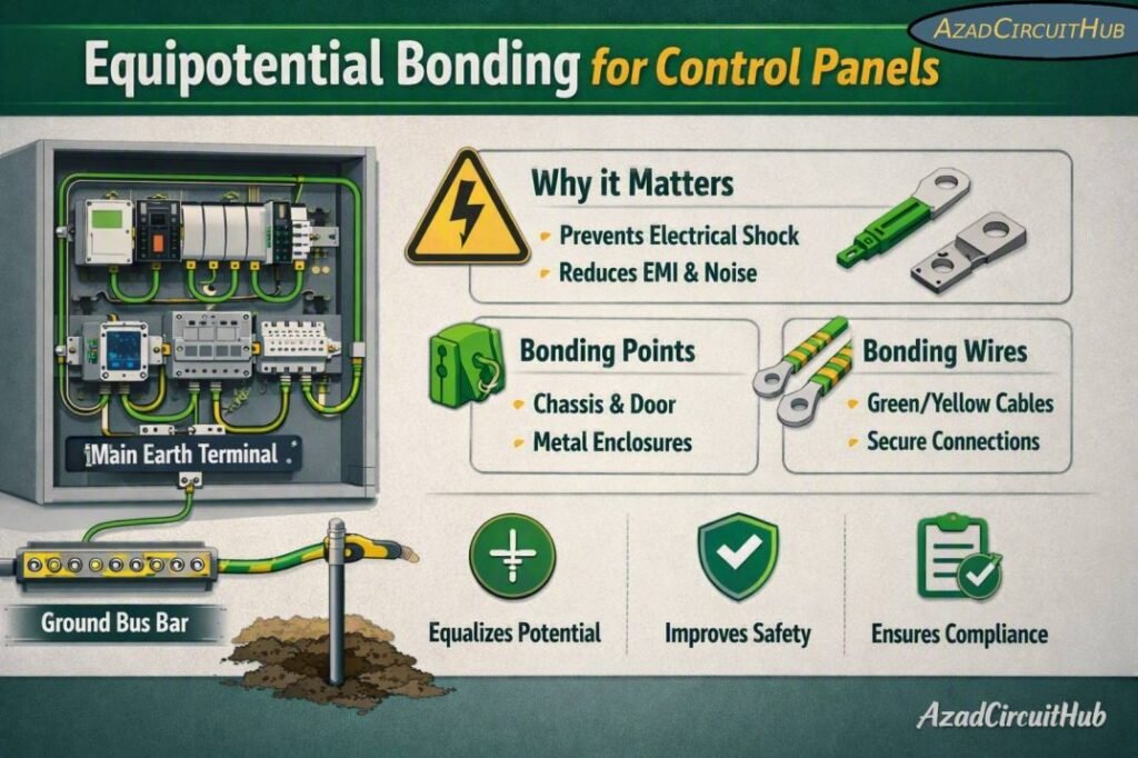
Table of Contents
Table of Contents
Equipotential Bonding for Control Panels: Quick Reference
| Design item | Typical requirement or practice | Main purpose |
|---|---|---|
| Panel enclosure | Bond to protective earth (PE) | Fault protection |
| Removable panel door | Flexible bonding strap where required | Maintain PE continuity |
| Mounting plate | Bond to PE where necessary | Fault-current path and EMC |
| DIN rail | Bond according to equipment design | PE/functional bonding |
| Cable gland | Bond metallic gland where required | Shield and PE continuity |
| Cable shield | Terminate according to EMC design | Reduce electrical noise |
| PE conductor | Size according to applicable standard | Protective bonding |
| Bonding connections | Short, direct and low impedance | Reduce fault and EMC impedance |
| Paint at bonding point | Remove or use approved bonding hardware | Reliable metal-to-metal contact |
| Verification | Continuity and protective measures tested | Confirm installation safety |
The exact conductor size and bonding arrangement must be selected from the applicable installation standard, fault-current conditions, equipment documentation, and protective-device requirements.
What Is Equipotential Bonding?
Equipotential bonding connects conductive parts together so that a dangerous potential difference does not develop between accessible components.
In an industrial control panel, this can include:
- Steel enclosure
- Inner mounting plate
- Panel door
- Removable covers
- Gland plates
- Metallic cable glands
- DIN rails
- PE terminal bar
- Machine frame
- Cable trays
- Metallic conduit
- Motor frames
- Instrument enclosures
Equipotential bonding for control panels is different from simply connecting one wire to the panel body. The complete bonding network must provide a dependable electrical path between relevant conductive parts.
For protective bonding, the objective is to provide a path that can carry fault current and allow the protective device to disconnect the faulty circuit within the required time.
For EMC bonding, the objective is often different. High-frequency noise requires low impedance, so a short, wide connection can perform better than a long thin wire even when both have adequate DC continuity.
Why Is Bonding Important in a Control Panel?
A control panel can contain power circuits and sensitive control electronics in the same enclosure. Variable frequency drives, contactors, switching power supplies, servo drives, relays, and motors can produce electrical interference.
Good bonding helps in several ways:
| Benefit | Effect on the system |
|---|---|
| Personnel protection | Reduces hazardous touch voltage |
| Fault clearing | Provides a suitable fault-current path |
| EMC control | Reduces common-mode interference |
| PLC reliability | Helps prevent unwanted resets and signal errors |
| Communication | Supports stable RS-485, Ethernet and fieldbus operation |
| Shield performance | Provides an effective reference and return path |
| Surge protection | Helps control transient voltage differences |
| Maintenance safety | Keeps accessible metalwork connected to PE |
A well-designed bonding system is especially important where a panel contains VFDs, servo systems, high-speed switching devices, instrumentation, or industrial communication networks.
For a broader grounding design, see our guide to the instrument earthing system to understand how protective, functional, and instrumentation grounding should be coordinated.
Main Components That Should Be Bonded
Not every metallic component automatically requires an individual bonding conductor. The design should establish whether reliable electrical continuity already exists and whether the component is part of the protective or functional bonding system.
Panel Door Bonding
A painted or powder-coated enclosure door may not provide dependable electrical continuity through its hinges. A flexible copper bonding strap is commonly used where the door forms part of the protective bonding arrangement.
The strap should be short enough to avoid unnecessary impedance and flexible enough to withstand repeated door movement.
Mounting Plate Bonding
The backplate often supports drives, PLC equipment, terminal blocks, power supplies, and other devices. Its bonding arrangement should be considered during panel construction rather than added after installation.
Gland Plate and Cable Entry
Metallic gland plates and cable glands can become part of the bonding network. This is particularly important for armoured cables and shielded cables.
The connection should not depend on paint, corrosion, or loose mechanical contact.
DIN Rail Bonding
DIN rails may provide mechanical mounting only, or they may form part of an intended electrical bonding path. The equipment manufacturer’s instructions should be followed. PE terminals mounted on DIN rails should have reliable contact with the intended protective circuit.
Recommended Bonding Arrangement
A practical panel arrangement normally starts with a dedicated PE terminal or PE bar.
| Connection | Recommended approach |
|---|---|
| Incoming PE | Connect directly to PE terminal/bar |
| Enclosure | Reliable metal bonding to PE |
| Door | Flexible bonding conductor if required |
| Mounting plate | Bond where required by design |
| Cable gland plate | Maintain protective continuity |
| Motor PE | Connect through the designated PE circuit |
| Cable shield | Terminate based on EMC requirements |
| Functional earth | Keep its purpose clearly defined |
| Instrument circuits | Follow system manufacturer’s grounding method |
Avoid creating random earth connections throughout the panel. A planned bonding architecture makes troubleshooting easier and reduces the possibility of circulating currents.
Protective Earth and Functional Earth
One of the most common sources of confusion is treating PE and functional earth as exactly the same thing.
Protective earth is primarily concerned with electrical safety. It provides a protective path for exposed conductive parts and supports automatic disconnection under fault conditions.
Functional earth, often associated with FE, is used for equipment operation, signal reference, EMC control, or interference reduction.
These functions can be connected within an engineered system, but they should not be mixed casually.
For sensitive instrumentation, the grounding arrangement should be designed according to the equipment manufacturer’s requirements and the applicable EMC standard.
Shield Bonding and EMC
Cable shielding is closely related to panel bonding. A shield may reduce interference only when it has a suitable termination and bonding arrangement.
For high-frequency EMC protection, a shield is often terminated with a large-area, low-inductance connection rather than a long pigtail. The correct method depends on the cable, frequency range, equipment design, and manufacturer’s EMC instructions.
| Application | Common EMC approach |
|---|---|
| Analog instrumentation | Carefully planned shield termination |
| RS-485 | Follow network and equipment grounding guidance |
| Ethernet | Use compatible shielded connectors and bonding |
| VFD motor cable | 360-degree shield termination is commonly preferred |
| Encoder cable | Follow drive and encoder manufacturer instructions |
| Thermocouple circuits | Avoid unnecessary ground loops |
| Sensitive control signals | Separate from high-power switching circuits |
The goal is not to ground every shield at random. The objective is to provide a controlled path for unwanted high-frequency currents while maintaining the required signal reference.
Bonding Conductor Size
There is no single universal conductor size that applies to every control panel. The required protective bonding conductor depends on the applicable standard and installation conditions.
IEC 60204-1 provides requirements for protective bonding of electrical equipment of machines, while IEC 61439 applies to low-voltage switchgear and controlgear assemblies. IEC 60364 provides broader electrical installation requirements.
The conductor should be selected considering:
- Fault current
- Protective-device characteristics
- Disconnection time
- Conductor material
- Cross-sectional area
- Mechanical protection
- Installation method
- Applicable standard
- Equipment manufacturer’s instructions
For a project-specific conductor selection, use our earth cable size calculator alongside the applicable installation and equipment requirements.
How to Make a Reliable Bonding Connection
A good mechanical connection is just as important as the selected conductor.
Follow these practical steps:
- Identify all conductive parts that require bonding.
- Establish the main PE terminal or bonding point.
- Use suitable copper conductors or approved bonding hardware.
- Remove insulating paint only where required for the bonding connection.
- Use suitable serrated washers, bonding terminals, or listed hardware where appropriate.
- Keep bonding conductors short and direct.
- Protect exposed connections against corrosion.
- Avoid relying on hinges as the only bonding path.
- Verify continuity after assembly.
- Document the bonding arrangement for future maintenance.
Do not use ordinary sheet-metal screws as a substitute for a properly engineered protective bonding connection.
Common Bonding Mistakes
Several installation practices can reduce the effectiveness of a panel bonding system.
| Mistake | Possible consequence | Better practice |
|---|---|---|
| Relying on painted surfaces | Poor electrical continuity | Use approved bonding points |
| Using door hinges as the only PE path | Uncertain continuity | Install bonding strap where required |
| Long shield pigtails | Higher EMC impedance | Use suitable shield termination |
| Undersized PE conductor | Safety risk during faults | Calculate/select according to standard |
| Random shield grounding | Ground-loop or noise problems | Follow system EMC design |
| Loose bonding hardware | Intermittent connection | Use proper torque and hardware |
| Mixing PE and signal returns | Noise and measurement errors | Separate functions logically |
| Ignoring corrosion | Increased contact resistance | Use suitable protected connections |
Testing Equipotential Bonding
Testing should form part of panel inspection and commissioning.
A continuity test can verify that the intended conductive parts are connected to the protective bonding circuit. The test method and acceptable limits should follow the applicable standard and equipment requirements.
A useful commissioning checklist includes:
| Test | What to verify |
|---|---|
| Visual inspection | Correct bonding hardware and routing |
| PE continuity | Conductive path between required points |
| Door bonding | Continuity maintained through movement |
| Gland plate | Reliable bonding connection |
| Cable shields | Correct termination |
| Protective devices | Correct rating and coordination |
| Insulation tests | No unintended leakage or breakdown |
| Functional tests | No abnormal control or communication faults |
For machinery, IEC 60204-1 includes specific verification requirements for protective bonding circuits. Always use the current edition adopted by the project or local authority.
Practical Design Example
Consider a steel control panel containing a PLC, 24 VDC power supply, VFD, motor starter, communication equipment, and shielded instrumentation cables.
The incoming protective conductor is connected to the panel PE terminal. The enclosure and required conductive mounting components are bonded to this protective circuit. The door receives a flexible bonding strap where required.
The VFD motor cable uses the manufacturer’s recommended shield termination. Sensitive instrument cables are routed separately from high-current switching cables. Functional earth connections are then implemented according to the PLC, instrumentation, and EMC design.
This arrangement provides a clear distinction between safety bonding and signal-related grounding while allowing the overall system to operate as one coordinated electrical installation.
Standards Related to Control Panel Bonding
| Standard | Relevance |
|---|---|
| IEC 60204-1 | Electrical equipment of machines and protective bonding |
| IEC 61439 | Low-voltage switchgear and controlgear assemblies |
| IEC 60364 | Low-voltage electrical installations |
| IEC 61000 series | EMC and electromagnetic compatibility |
| IEC 60533 | EMC considerations for electrical/electronic systems in ships |
| NFPA 70 (NEC) | Electrical installation requirements in the United States |
| UL 508A | Industrial control panels in the United States |
The applicable standard depends on the equipment type, country, installation, and certification requirements. Manufacturer instructions and local electrical regulations should always be checked before finalizing a bonding design.
Final Checklist
Before energizing a control panel, confirm:
- PE connection is secure.
- Enclosure bonding is continuous.
- Door bonding is provided where necessary.
- Mounting components have the required continuity.
- Metallic cable entry components are correctly bonded.
- Shield terminations follow the EMC design.
- Protective and functional earthing purposes are understood.
- Bonding conductors are correctly selected.
- Connections are mechanically secure.
- Required continuity and safety tests have been completed.
- Test results are recorded.
Good equipotential bonding for control panels is not simply about adding more earth wires. It is about creating a deliberate, low-impedance and verifiable bonding network that supports both electrical safety and reliable equipment operation.
For larger industrial installations, the panel should be treated as one part of the complete grounding architecture. The relationship between panel PE, instrument earth, cable shields, machine frames, cable trays, and the main earthing system should be established before installation.
FAQs
What is equipotential bonding in a control panel?
Equipotential bonding connects accessible conductive parts so that dangerous voltage differences are minimized during faults and normal operation. In a control panel, this can include the enclosure, door, mounting plate, gland plate, PE bar, and other conductive components.
Does a control panel door need an earth bonding wire?
A flexible bonding conductor is commonly used when the door is part of the protective bonding arrangement and the hinges cannot be relied upon to maintain the required electrical continuity. The final arrangement should comply with the applicable equipment standard.
What size should a control panel bonding conductor be?
There is no universal size for every control panel. The protective bonding conductor should be selected using the applicable standard, fault current, disconnection time, conductor characteristics, and equipment requirements. IEC 60204-1 and IEC 61439 are important references depending on the application.
Should cable shields be connected to the control panel earth?
Shield termination depends on the cable type, signal, equipment design, EMC requirements, and frequency range. For many high-frequency or VFD applications, a short or 360-degree shield termination provides better EMC performance than a long pigtail.
What is the difference between protective earth and functional earth?
Protective earth is primarily intended for electrical safety and fault protection. Functional earth is used for equipment operation, signal reference, EMC control, or interference reduction. They may be interconnected in a controlled system, but their functions should not be confused.
Get new guides in your feed. Follow Electrical Insights on LinkedIn for new electrical standards guides, calculators and design tips from Azad Circuit Hub.
#EquipotentialBonding, #ControlPanels, #ElectricalBonding, #ControlPanelGrounding, #IECStandards, #ElectricalSafety, #PanelEarthing, #GroundingSystems, #IndustrialAutomation, #ElectricalEngineering
