
Typical Contact Resistance Values for Electrical Equipment (Reference Table)
Typical Contact Resistance Values are useful benchmarks when testing breakers, switches, relays, busbars, contactors, disconnects, and other electrical connections. A low and stable resistance usually indicates a sound conductive path, while an unusually high reading can point to oxidation, loose joints, damaged contacts, contamination, or mechanical wear.
Contact resistance is normally measured with a low-resistance ohmmeter (DLRO) or micro-ohmmeter that applies a controlled test current. Because the expected value depends on the equipment type, rating, contact design, and test method, there is no single resistance value that applies to every device.
The following reference table provides practical ranges commonly encountered in electrical maintenance and commissioning.
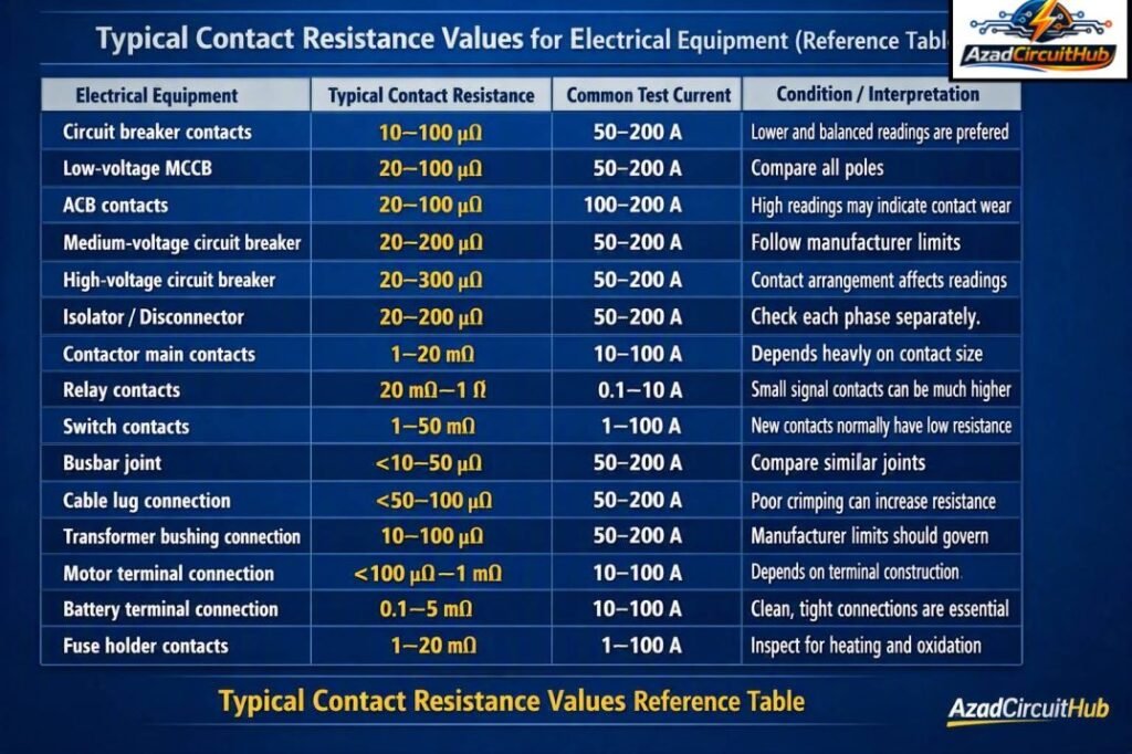
Table of Contents
Table of Contents
Typical Contact Resistance Values Reference Table
| Electrical Equipment | Typical Contact Resistance | Common Test Current | Condition/Interpretation |
|---|---|---|---|
| Circuit breaker contacts | 10–100 µΩ | 50–200 A | Lower and balanced readings are preferred |
| Low-voltage MCCB | 20–100 µΩ | 50–200 A | Compare all poles |
| ACB contacts | 20–100 µΩ | 100–200 A | High readings may indicate contact wear |
| Medium-voltage circuit breaker | 20–200 µΩ | 50–200 A | Follow manufacturer limits |
| High-voltage circuit breaker | 20–300 µΩ | 50–200 A | Contact arrangement affects readings |
| Isolator/disconnector | 20–200 µΩ | 50–200 A | Check each phase separately |
| Contactor main contacts | 1–20 mΩ | 10–100 A | Depends heavily on contact size |
| Relay contacts | 20 mΩ–1 Ω | 0.1–10 A | Small signal contacts can be much higher |
| Switch contacts | 1–50 mΩ | 1–100 A | New contacts normally have low resistance |
| Busbar joint | <10–50 µΩ | 50–200 A | Compare similar joints |
| Cable lug connection | <50–100 µΩ | 50–200 A | Poor crimping can increase resistance |
| Transformer bushing connection | 10–100 µΩ | 50–200 A | Manufacturer limits should govern |
| Motor terminal connection | <100 µΩ–1 mΩ | 10–100 A | Depends on terminal construction |
| Battery terminal connection | 0.1–5 mΩ | 10–100 A | Clean, tight connections are essential |
| Fuse holder contacts | 1–20 mΩ | 1–100 A | Inspect for heating and oxidation |
These figures are general field reference ranges, not universal acceptance limits. The equipment manufacturer’s specification and applicable testing standard should always take priority.
What Is Contact Resistance?
Contact resistance is the electrical resistance that exists at the interface between two conductive surfaces. Even when two metal surfaces appear to touch perfectly, current does not flow through the entire visible contact area.
Microscopic surface irregularities create small conductive paths called contact spots or asperities. Oxidation, dirt, corrosion, pressure, surface finish, temperature, and mechanical condition can all affect the measured resistance.
The value is usually very small, so a conventional digital multimeter is often unsuitable for accurate measurement.
For example, a circuit breaker may have a contact resistance of only 30 µΩ. A standard multimeter may not have the accuracy, resolution, or test current needed to measure this value reliably.
Contact Resistance Values by Equipment Type
Different electrical devices have different acceptable resistance characteristics. A heavy-duty circuit breaker designed to carry thousands of amperes should generally have a much lower resistance than a small control relay.
Circuit Breakers
Circuit breaker contact resistance is one of the most important low-resistance measurements performed during commissioning and preventive maintenance.
Typical readings for LV and MV breakers are often in the tens or low hundreds of micro-ohms. The exact value depends on the breaker design, frame size, contact material, pole construction, and manufacturer’s specifications.
A useful field practice is to compare the resistance of all three phases. A significantly higher reading on one pole deserves investigation even if the absolute value appears reasonable.
Disconnect Switches and Isolators
Disconnector contact resistance can increase because of oxidation, contamination, inadequate contact pressure, or mechanical alignment problems.
Typical Contact Resistance Values for disconnectors are often around 20–200 µΩ, although actual limits vary substantially between designs.
For outdoor equipment, environmental exposure is especially important. Moisture, dust, salt, and corrosion can affect the contact surface and create localized heating.
Contactors
Contactors generally have higher resistance than large circuit breakers because their main contacts are smaller.
A healthy power contactor may show resistance in the low milliohm range. Readings should be compared between poles and against the manufacturer’s data.
If one pole has substantially greater resistance than the others, inspect the contact surface, spring pressure, terminal connection, and contact wear.
Relays
Relay contact resistance can vary much more than power equipment. Small signal relays may have resistance measured in tens or hundreds of milliohms, while worn or contaminated contacts can show substantially higher values.
Relay contact resistance is especially important in control circuits where even a small voltage drop can affect sensitive equipment.
Busbar Joint Contact Resistance
Busbar joints are another important application for low-resistance testing. A bolted joint should provide a low-resistance path capable of carrying the rated current without excessive heating.
| Busbar Connection | Typical Reading | What to Check if High |
|---|---|---|
| Copper-to-copper joint | <10–30 µΩ | Torque, oxidation, joint surface |
| Aluminum-to-aluminum joint | <20–50 µΩ | Oxide layer and joint preparation |
| Copper-to-aluminum joint | <30–100 µΩ | Joint compound and bimetallic connection |
| Flexible busbar connection | <50–100 µΩ | Crimp and mechanical condition |
| Cable lug to busbar | <50–100 µΩ | Lug crimp and bolt torque |
The important point is not simply obtaining the lowest possible number. Consistent readings across comparable connections are often more useful for identifying a developing problem.
For detailed testing procedures, test currents, lead compensation, and applicable standards, see our guide to contact resistance test iec standard requirements before establishing an acceptance criterion.
How Contact Resistance Is Measured
A four-wire Kelvin measurement is the preferred technique for very low resistance measurements.
The test instrument sends a relatively high, controlled current through the equipment under test. Separate voltage-sensing leads measure the voltage drop across the contact.
Resistance is then calculated using Ohm’s law:
R = V / I
For example, if a test current of 100 A produces a voltage drop of 5 mV:
R = 0.005 / 100
R = 0.00005 Ω
Therefore:
R = 50 µΩ
The four-wire method minimizes the effect of test-lead and connection resistance, which is critical when measuring micro-ohm values.
Why Test Current Matters
Test current has a major effect on the reliability of low-resistance measurements.
A very low test current may not provide enough voltage drop for an accurate measurement. It may also fail to produce a representative result across contaminated or oxidized contact surfaces.
High-current micro-ohm testers are therefore commonly used for circuit breakers, busbar joints, disconnectors, and high-current connections.
The selected test current should always follow the equipment manufacturer’s instructions and the applicable test procedure.
Factors That Affect Contact Resistance
Several conditions can cause Contact Resistance Values to change.
- Contact surface oxidation
- Corrosion
- Dust and contamination
- Loose mechanical connections
- Incorrect contact pressure
- Contact wear or pitting
- Poor cable termination
- Improper crimping
- Excessive temperature
- Mechanical misalignment
- Surface finish and contact material
- Previous thermal damage
Temperature is particularly important because metal resistance changes with temperature. Measurements made at significantly different temperatures may not be directly comparable.
High Contact Resistance: What Does It Mean?
A high resistance reading does not automatically mean the equipment has failed. The result should be evaluated against the manufacturer’s limit, previous test records, phase-to-phase comparison, and equipment condition.
For example, suppose a three-phase breaker produces:
| Phase | Resistance |
|---|---|
| L1 | 38 µΩ |
| L2 | 41 µΩ |
| L3 | 95 µΩ |
The L3 reading is considerably higher than the other two phases. Even though 95 µΩ may fall within some equipment limits, the imbalance warrants investigation.
Possible causes include a damaged contact, contamination, insufficient contact pressure, or a poor terminal connection.
Contact Resistance Testing Acceptance Criteria
There is no universal pass/fail value for every electrical device.
A proper assessment should consider:
- Manufacturer’s resistance limit
- Equipment voltage and current rating
- Applicable IEC or other testing standard
- Previous maintenance results
- Phase-to-phase comparison
- Test current
- Ambient and equipment temperature
- Measurement repeatability
This approach prevents a common testing mistake: rejecting equipment solely because its resistance does not match a generic reference table.
If you need the correct test method and standard-based guidance, use our detailed contact resistance test iec standard guide to understand applicable procedures and acceptance considerations.
Contact Resistance vs Insulation Resistance
These two tests measure completely different electrical properties.
| Test | Measures | Typical Unit | Main Purpose |
|---|---|---|---|
| Contact resistance test | Resistance through conductive contacts | µΩ or mΩ | Find poor connections and contact problems |
| Insulation resistance test | Resistance through insulation | MΩ or GΩ | Find insulation deterioration |
| Continuity test | Presence of a conductive path | Ω | Verify electrical continuity |
| Earth resistance test | Resistance of grounding system | Ω | Assess grounding performance |
A low contact resistance does not prove that insulation is healthy. Likewise, excellent insulation resistance does not guarantee that a high-current connection has low contact resistance.
How Often Should Contact Resistance Be Tested?
Testing frequency depends on the equipment, operating environment, criticality, and maintenance program.
High-voltage breakers, major switchgear, substations, and critical industrial connections may be tested during commissioning and scheduled maintenance. Equipment operating in dusty, humid, corrosive, or high-temperature environments may require more frequent inspection.
Trend analysis is particularly valuable. A gradual increase over several maintenance cycles can identify deterioration before it causes overheating or an operational failure.
Best Practices for Accurate Contact Resistance Testing
Follow these practices when performing a low-resistance test:
- Isolate and properly de-energize the equipment.
- Apply the required safety and lockout/tagout procedures.
- Clean accessible test points when appropriate.
- Use a calibrated micro-ohmmeter or DLRO.
- Use Kelvin four-wire connections.
- Select the recommended test current.
- Keep test lead connections clean and secure.
- Record temperature and test conditions.
- Test every phase or contact where applicable.
- Compare results with previous measurements.
- Follow the manufacturer’s acceptance limits.
Never rely on a generic Typical Contact Resistance Values table as a substitute for the equipment manufacturer’s test specification.
Reference Summary
| Equipment | Typical Range | Primary Concern |
|---|---|---|
| LV circuit breaker | 10–100 µΩ | Contact condition |
| MV circuit breaker | 20–200 µΩ | Contact wear and pressure |
| ACB | 20–100 µΩ | Pole consistency |
| Isolator | 20–200 µΩ | Oxidation and alignment |
| Contactor | 1–20 mΩ | Contact wear |
| Relay | 20 mΩ–1 Ω | Contact contamination |
| Busbar joint | <10–50 µΩ | Joint quality |
| Cable lug | <50–100 µΩ | Crimp and torque |
| Battery connection | 0.1–5 mΩ | Terminal condition |
Frequently Asked Questions
What are typical contact resistance values for a circuit breaker?
Typical readings for many circuit breakers fall between approximately 10 and 200 µΩ, depending on breaker type, rating, and construction. The manufacturer’s specified limit is the correct acceptance criterion.
What is a good contact resistance value?
A good value is one that remains below the equipment manufacturer’s specified maximum and is reasonably consistent between phases or comparable contacts. Lower resistance is generally desirable, but the test conditions must also be considered.
Can I measure contact resistance with a normal multimeter?
A standard multimeter is generally not suitable for accurate micro-ohm measurements. A four-wire low-resistance ohmmeter or micro-ohmmeter provides much better accuracy for high-current electrical equipment.
Why does contact resistance increase?
Common causes include oxidation, corrosion, loose connections, worn contacts, inadequate contact pressure, contamination, poor crimping, and thermal damage.
What is the difference between contact resistance and insulation resistance?
Contact resistance measures resistance through a conductive connection and is normally expressed in micro-ohms or milliohms. Insulation resistance measures leakage through insulation and is normally expressed in megohms or gigohms.
Final Takeaway
Typical Contact Resistance Values provide a useful starting point for electrical testing, but they should never be treated as universal pass/fail limits. Circuit breakers, disconnectors, contactors, relays, busbar joints, and cable connections all have different resistance characteristics.
The most reliable approach combines a calibrated low-resistance tester, an appropriate test current, four-wire measurement technique, manufacturer specifications, and historical test data. Comparing phases and tracking resistance over time can often reveal developing contact problems before they result in excessive heating, equipment damage, or an unexpected outage.
For a deeper reference on international testing requirements and measurement practices, review our contact resistance test iec standard guide alongside the equipment manufacturer’s instructions.
Get new guides in your feed. Follow Electrical Insights on LinkedIn for new electrical standards guides, calculators and design tips from Azad Circuit Hub.
#ContactResistance, #ElectricalEquipment, #ElectricalTesting, #ResistanceTesting, #ElectricalMaintenance, #ElectricalEngineering, #CircuitBreakers, #BusbarTesting, #SwitchgearTesting, #ElectricalSafety
