Contact Resistance Testing: Why, When and How Often to Test
Contact resistance testing is used to check the electrical resistance of joints, switchgear contacts, circuit breaker connections, busbar joints, disconnectors, and other high-current connections. A low and stable resistance helps confirm that current can pass through the connection without creating excessive heat or voltage drop.
The test is especially important in substations, industrial plants, power distribution systems, motor control centers, and high-current equipment. A small increase in resistance at a bolted or switching connection can produce significant heating when the circuit carries a high current.
| Item | Typical Test Purpose | Common Test Current |
|---|---|---|
| Circuit breaker contacts | Check main contact condition | 50–200 A DC |
| Busbar joints | Verify bolted connection quality | 50–200 A DC |
| Disconnect switches | Check contact and connection condition | 50–200 A DC |
| Cable lugs | Verify termination quality | 10–100 A DC |
| Transformer connections | Check high-current joints | 50–200 A DC |
| Motor connections | Check terminal and lug resistance | 10–100 A DC |
Actual test current and acceptance limits depend on the equipment manufacturer, applicable standard, and test procedure.
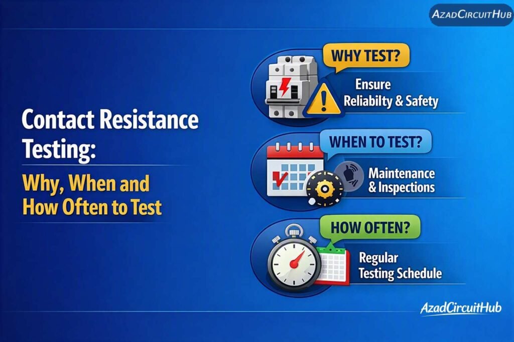
Table of Contents
Table of Contents
What Is Contact Resistance Testing?
Contact resistance testing measures the resistance of an electrical connection under controlled conditions. A specialized low-resistance ohmmeter, often called a DLRO or micro-ohmmeter, injects DC current through the connection and measures the resulting voltage drop.
The basic relationship is:
R = V / I
Where:
- R = resistance in ohms
- V = measured voltage drop
- I = injected test current
Because the resistance of power connections is normally very low, measurements are commonly expressed in micro-ohms (µΩ).
A four-wire Kelvin measurement is normally used for accurate low-resistance testing. Two leads carry the test current while two separate sensing leads measure the voltage directly across the connection.
Why Contact Resistance Testing Is Important
High contact resistance can cause localized heating. The problem may begin with a slightly loose connection, oxidation, contamination, damaged contact surfaces, inadequate contact pressure, or mechanical wear.
As current increases, the heat generated by resistance follows:
P = I²R
This means even a small increase in resistance can produce substantial additional heating at high current.
| Condition | Possible Effect |
|---|---|
| Loose connection | Increased resistance and heating |
| Oxidized contact | Unstable or elevated resistance |
| Damaged contact surface | Poor current transfer |
| Low contact pressure | Increased contact resistance |
| Contamination | Poor electrical contact |
| Mechanical wear | Increasing resistance over time |
| Incorrect torque | Connection may loosen or overheat |
Trending resistance measurements over several maintenance periods can be more useful than looking at one reading in isolation.
When Should Contact Resistance Testing Be Performed?
Contact resistance testing is commonly performed during commissioning, preventive maintenance, major equipment servicing, and troubleshooting.
A practical maintenance program may include testing at the following stages:
| Situation | Recommended Action |
|---|---|
| New equipment commissioning | Establish baseline |
| After major maintenance | Confirm connection condition |
| Circuit breaker overhaul | Test main contacts |
| Busbar modification | Test affected joints |
| Abnormal temperature detected | Test as part of investigation |
| Repeated breaker problems | Test and compare phases |
| Periodic maintenance | Trend results |
| After connection tightening | Verify improvement |
The manufacturer’s maintenance instructions should take priority where they specify a particular test interval or procedure.
How Is Contact Resistance Testing Performed?
Before testing, isolate the equipment according to the site’s electrical safety procedure. Confirm that the circuit is de-energized, locked out, and properly discharged where required.
A typical test sequence is:
- Identify the connection or contact being tested.
- Isolate and secure the equipment.
- Verify the absence of voltage.
- Clean suitable test points if required.
- Connect the current leads.
- Connect the voltage-sensing leads close to the contact under test.
- Select the manufacturer’s recommended test current.
- Inject DC current.
- Record the stabilized resistance.
- Repeat the measurement on other phases or connections.
- Compare the results with manufacturer limits and previous readings.
- Remove the test equipment and restore the system safely.
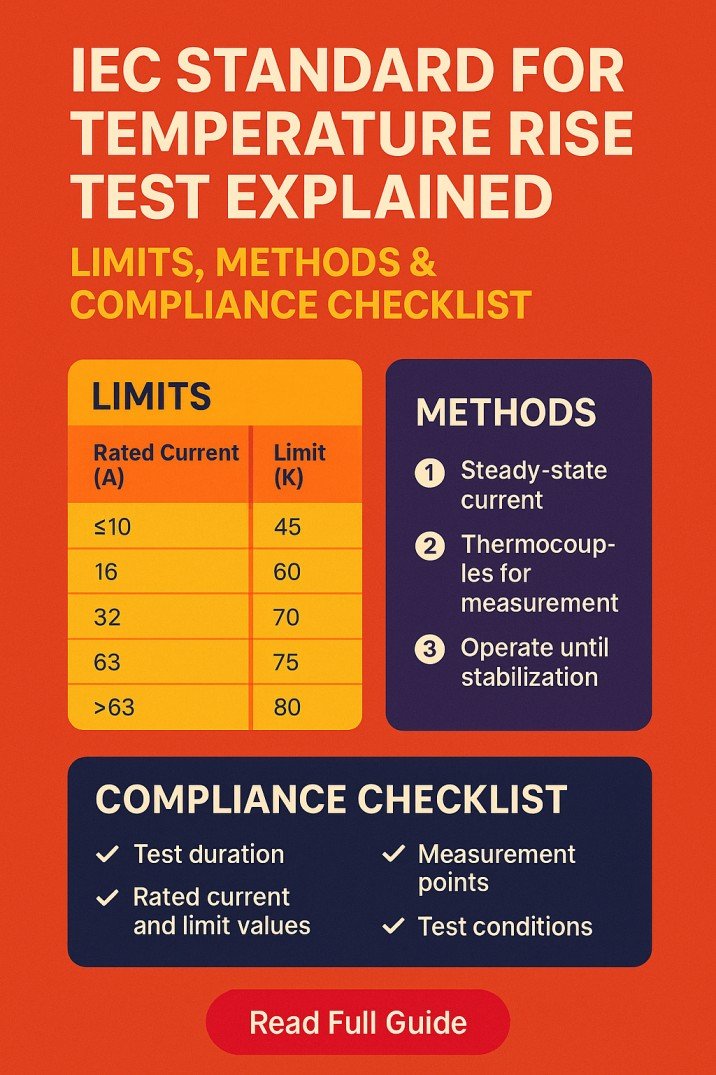
For a reference covering applicable requirements and methods, see contact resistance test iec standard.
What Test Current Should Be Used?
A higher test current generally improves measurement stability because it creates a larger voltage signal across a very low resistance. However, the test current must be suitable for the equipment and manufacturer’s procedure.
Many low-resistance testers provide currents such as 10 A, 50 A, 100 A, or 200 A DC.
| Test Current | Typical Use |
|---|---|
| 10 A | Smaller connections and control applications |
| 50 A | General low-resistance measurements |
| 100 A | Power connections and switchgear |
| 200 A | High-current equipment and demanding applications |
The highest available test current is not automatically the correct choice. Follow the equipment test procedure and manufacturer’s instructions.
How Often Should Contact Resistance Testing Be Done?
There is no single maintenance interval that applies to every electrical installation. Testing frequency depends on equipment type, operating conditions, manufacturer instructions, duty cycle, fault history, and the consequences of failure.
A condition-based approach is often useful.
| Equipment / Condition | Typical Approach |
|---|---|
| Critical switchgear | Periodic testing and trending |
| Frequently operated breakers | Test during scheduled maintenance |
| Outdoor disconnectors | Inspect and test based on environment |
| High-load connections | Include in planned maintenance |
| Equipment with thermal alarms | Test promptly |
| Recently repaired connections | Establish a new baseline |
| Stable low-risk equipment | Follow planned maintenance interval |
For detailed guidance on maintenance practices, compare the applicable contact resistance test standard with the equipment manufacturer’s maintenance documentation.
How to Interpret Contact Resistance Results
There is no universal resistance value that can be applied to every breaker, switch, busbar joint, or terminal. Contact construction, rated current, contact material, connection design, and manufacturer specifications all affect the expected value.
The most useful comparison is often between identical phases or poles and against previous measurements from the same equipment.
For example, if three breaker poles produce measurements of 24 µΩ, 25 µΩ, and 41 µΩ, the higher reading deserves investigation even before a final pass/fail decision is made.
Review:
- Manufacturer acceptance limits
- Previous test results
- Phase-to-phase differences
- Resistance trend
- Ambient and equipment conditions
- Test current
- Test lead arrangement
- Connection cleanliness
Use a dedicated reference for typical contact resistance values when comparing readings with commonly encountered ranges.
Common Causes of High Contact Resistance
High resistance does not always mean that a contact itself is defective. The test setup and external connections should also be checked.
Common causes include:
- Loose bolted connections
- Corrosion or oxidation
- Dirty contact surfaces
- Incorrect contact pressure
- Worn breaker contacts
- Damaged terminals
- Poor crimping
- Incorrect assembly
- Mechanical misalignment
- Inadequate maintenance
If one phase produces a substantially different result from the others, inspect the complete current path rather than replacing a component immediately.
Frequently Asked Questions
What is a good contact resistance value?
There is no single value that applies to every electrical connection. The acceptable value depends on equipment design and manufacturer specifications. For maintenance, previous readings and phase-to-phase comparisons are also useful.
What instrument is used for contact resistance testing?
A low-resistance ohmmeter, micro-ohmmeter, or DLRO is commonly used. These instruments normally use a four-wire Kelvin measurement to reduce the influence of test lead resistance.
Why is DC used for contact resistance testing?
DC allows the instrument to inject a controlled current and measure the resulting voltage drop across the connection. This provides a direct low-resistance measurement using Ohm’s law.
How often should circuit breaker contact resistance be tested?
The interval depends on the breaker manufacturer, service conditions, operating frequency, maintenance program, and applicable standards. Testing is commonly included during commissioning and scheduled breaker maintenance.
What causes contact resistance to increase?
Loose connections, oxidation, contamination, contact wear, insufficient contact pressure, corrosion, mechanical damage, and poor termination can all increase measured resistance.
Final Takeaway
Contact resistance testing provides an important condition check for high-current electrical connections. A good maintenance program does more than record a single resistance value. It establishes a baseline, repeats measurements under controlled conditions, compares similar phases, and tracks changes over time.
For critical switchgear and power connections, combining resistance measurements with visual inspection, torque verification, thermal imaging, and equipment maintenance records can provide a clearer picture of connection condition. Always use the equipment manufacturer’s limits and the applicable electrical standard when making a final maintenance decision.
Get new guides in your feed. Follow Electrical Insights on LinkedIn for new electrical standards guides, calculators and design tips from Azad Circuit Hub.
#ContactResistanceTesting, #ElectricalTesting, #ResistanceTesting, #ElectricalMaintenance, #CircuitBreakerTesting, #SwitchgearTesting, #ElectricalSafety, #MicroOhmmeter, #PreventiveMaintenance, #PowerSystems