Derating Busbar Capacity for Temperature and Altitude: Best Guide
Derating busbar capacity for temperature and altitude is essential when designing electrical panels, switchgear, and power distribution systems. High ambient temperatures reduce heat dissipation, while high-altitude installations can affect cooling and insulation performance. Engineers must account for both conditions before selecting a copper or aluminum busbar.
| Design Parameter | Effect on Busbar | Required Action |
|---|---|---|
| High ambient temperature | Reduces available thermal margin | Verify temperature rise and apply suitable derating |
| High altitude | Reduces air density and cooling | Check manufacturer altitude limits and correction factors |
| Enclosed switchgear | Restricts heat dissipation | Assess internal temperature and ventilation |
| Closely spaced bars | Increases mutual heating | Check spacing and busbar arrangement |
| Continuous high load | Raises conductor temperature | Verify continuous current rating |
| Copper vs. aluminum | Different electrical resistance and thermal properties | Use material-specific ratings |
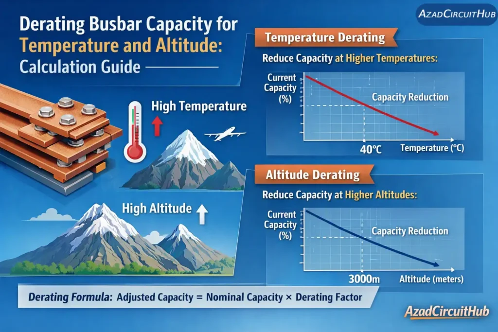
Table of Contents
Table of Contents
Why Busbar Capacity Must Be Derated
A busbar carries current by conducting electricity through a copper or aluminum strip. Its resistance generates heat, and that heat must escape into the surrounding air and supporting structure.
At higher ambient temperatures, the difference between the busbar temperature and the surrounding air becomes smaller. The bar therefore has less thermal margin before reaching its permitted operating temperature.
At high altitude, thinner air reduces convective cooling. This can increase busbar temperature under the same load, particularly in enclosed switchgear. Insulation strength and equipment performance may also require attention.
Derating busbar capacity for temperature and altitude helps prevent overheating, excessive thermal expansion, insulation damage, and premature failure.
Derating Busbar Capacity for Temperature and Altitude
Temperature Derating of Busbar Current Capacity
Busbar ampacity depends on conductor material, dimensions, surface finish, orientation, spacing, enclosure design, and allowable temperature rise. A busbar rated at one ambient temperature may not safely carry the same current at a higher ambient temperature.
A basic thermal relationship is:
P = I² × R
Where:
- P = heat generated in watts
- I = current in amperes
- R = conductor resistance in ohms
As current increases, heat generation rises with the square of current. This is why even a modest increase in load can significantly increase busbar temperature.
For a preliminary estimate, engineers sometimes use a thermal-resistance model:
I₂ = I₁ × √[(T₂ − Tₐ₂) / (T₁ − Tₐ₁)]
Where:
- I₁ = known current rating
- I₂ = estimated adjusted current
- T₁ and T₂ = permitted conductor temperatures under the respective conditions
- Tₐ₁ and Tₐ₂ = corresponding ambient temperatures
This formula assumes unchanged resistance and thermal resistance. It is only a simplified estimate, not a universal busbar derating formula. Actual ratings must be verified against tested equipment data or manufacturer tables.
Example: Temperature Derating
Suppose a copper busbar has a verified 1,000 A rating at an ambient temperature of 40°C. Assume a permitted conductor temperature of 90°C and a new ambient temperature of 50°C.
Using the simplified thermal model:
I₂ = 1,000 × √[(90 − 50) / (90 − 40)]
I₂ = 1,000 × √(40 / 50)
I₂ ≈ 894 A
The preliminary estimate is approximately 894 A. Do not use this value as a final design rating unless the manufacturer’s rating basis and applicable equipment standard support the assumptions.
For a detailed initial estimate, use the Busbar Current Carrying Capacity Calculator and verify the result against the actual installation conditions.
Altitude Derating of Busbar Capacity
Altitude affects electrical equipment in two important ways: cooling and insulation performance. Air density decreases as elevation increases, which reduces convective heat transfer. The extent of the effect depends on enclosure design, airflow, bar arrangement, and equipment construction.
| Installation Altitude | Design Consideration |
|---|---|
| Up to 1,000 m | Common reference range for many low-voltage equipment ratings |
| Above 1,000 m | Check manufacturer altitude provisions |
| Around 2,000 m | Assess cooling and insulation requirements |
| Around 3,000 m | Obtain altitude-specific equipment ratings or correction guidance |
| Above 4,000 m | Require careful verification of insulation coordination and thermal performance |
These are screening ranges, not universal derating thresholds. The applicable correction depends on the equipment and governing standard.
IEC 61439-1, Clause 7.1, addresses service conditions for low-voltage switchgear and controlgear assemblies, including altitude-related conditions. IEC 60664-1 covers insulation coordination for equipment within its scope. Check the applicable editions and product-specific requirements before applying correction factors.
NEC Article 110, including 110.3(B), requires listed or labeled equipment to be installed and used in accordance with instructions included in the listing or labeling. NEC does not provide one universal busbar altitude derating factor for every installation.
Combined Temperature and Altitude Derating
When both conditions apply, do not automatically multiply two correction factors unless the manufacturer or an approved engineering method supports that approach.
A preliminary calculation may be expressed as:
I_adjusted = I_rated × K_temperature × K_altitude
Where:
- I_adjusted = estimated current capacity under site conditions
- I_rated = verified reference rating
- K_temperature = applicable temperature correction factor
- K_altitude = applicable altitude correction factor
Both factors must come from suitable manufacturer data, tested performance, or a validated engineering method. Avoid applying a correction twice if the published rating already accounts for the relevant conditions.
| Factor | Information to Confirm |
|---|---|
| Reference rating | Rated current and reference ambient temperature |
| Temperature factor | Manufacturer’s correction data |
| Altitude factor | Manufacturer’s altitude guidance |
| Enclosure | IP rating, ventilation, and internal temperature |
| Busbar configuration | Dimensions, orientation, spacing, and number of bars |
| Final verification | Temperature rise and assembly compliance |
Compare copper and aluminum designs using the aluminum bus bar ampacity chart where relevant, but do not assume that equal dimensions or equal correction factors produce equal current ratings.
Standards and Practical Design Checks
IEC 61439-1 and IEC 61439-2 are key references for low-voltage switchgear and controlgear assemblies. They address assembly design verification and temperature-rise performance within their respective scopes. The applicable product standard and verification method determine how the assembly rating must be established.
For US installations, consult NEC Article 110 for equipment installation requirements and NEC Article 310 where applicable to conductor ampacity. These provisions do not replace verification of a switchgear busbar’s rated current and temperature-rise performance.
Before approving a design, check:
- Continuous load current and expected duty cycle.
- Copper or aluminum grade and bar dimensions.
- Ambient temperature and altitude at the installation site.
- Enclosure ventilation and internal temperature.
- Joint resistance, contact pressure, and connection hardware.
- Short-circuit withstand rating and protective-device coordination.
- Manufacturer instructions and applicable standards.
Use the busbar current carrying capacity chart as an initial reference, then confirm the selected bar against the actual switchgear design.
Expert Engineering Insight
In practical panel design, busbar overheating often comes from more than conductor size alone. Poor joints, crowded layouts, restricted airflow, and hot enclosures can undermine a seemingly adequate rating. I always treat the complete assembly and its operating environment as part of the current-capacity assessment.
Frequently Asked Questions
1. How to calculate busbar capacity?
Start with the manufacturer’s rated current for the exact bar arrangement. Confirm conductor material, dimensions, ambient temperature, enclosure, and altitude. Apply only verified correction factors, then check temperature rise and short-circuit withstand capability.
Use a verified reference rating and manufacturer-approved corrections. A cross-sectional-area calculation alone cannot establish a safe busbar ampacity.
2. How many amps can a busbar handle?
The capacity depends on its material, cross-sectional area, shape, spacing, cooling, and permitted temperature rise. Two busbars with the same cross-sectional area may have different ratings if their installations differ.
Use the rated current for the actual busbar configuration rather than relying on a universal amps-per-square-millimeter value.
3. What size copper busbar is required for a 250 amp rating?
The required dimensions depend on ambient temperature, enclosure design, installation method, and temperature-rise limits. A 250 A rating cannot be guaranteed by width and thickness alone.
Select a copper bar with a documented 250 A or higher rating under the intended conditions, and verify the complete assembly.
4. How do you size a busbar?
Determine the design current, material, allowable temperature rise, short-circuit withstand requirement, and installation conditions. Select a suitable manufacturer-rated configuration and verify thermal and mechanical performance.
Size the busbar for continuous current first, then verify temperature rise, fault withstand, joints, and applicable standards.
5. How many amps should my bus bar be?
The busbar should support the required continuous load and any applicable design margin while remaining within its rated temperature and fault limits.
Base the rating on calculated demand, equipment requirements, and applicable code rules, not simply the main breaker rating.
6. What is the size of a busbar for 100A?
There is no single width-and-thickness combination that guarantees 100 A under every condition. Copper and aluminum bars have different properties, and enclosure temperature can change their usable capacity.
Choose a busbar with a verified rating of at least 100 A for the actual installation conditions, including temperature and altitude.
Final Recommendation
Derating busbar capacity for temperature and altitude requires more than applying a generic percentage. Use verified ratings, assess the complete assembly, and confirm the manufacturer’s correction data. This approach helps maintain safe operating temperatures, reliable connections, and compliance with applicable IEC or NEC requirements.
Get new guides in your feed. Follow Electrical Insights on LinkedIn for new electrical standards guides, calculators and design tips from Azad Circuit Hub.