
High Impedance Differential Protection Calculation: Formula, Steps, and Example
High impedance differential protection is widely used for transformer, busbar, generator, and motor protection where fast and stable operation is required during internal faults. Unlike low impedance differential schemes, the high impedance method uses a high relay impedance and stabilizing resistor to prevent unwanted relay operation during heavy external faults.
A correct High Impedance Differential Protection Calculation must consider the current transformer (CT) ratio, CT secondary resistance, lead resistance, relay burden, stabilizing resistor, and fault current. The objective is to ensure that the relay operates for internal faults while remaining stable for through-fault conditions.
| Parameter | Typical consideration |
|---|---|
| Protection principle | High impedance differential |
| Main components | CTs, relay, stabilizing resistor |
| CT connection | Usually parallel connected |
| Key calculation | Stabilizing voltage and resistor |
| Main purpose | Internal fault protection |
| Stability requirement | No false operation during external faults |
| Common applications | Busbars, transformers, generators |
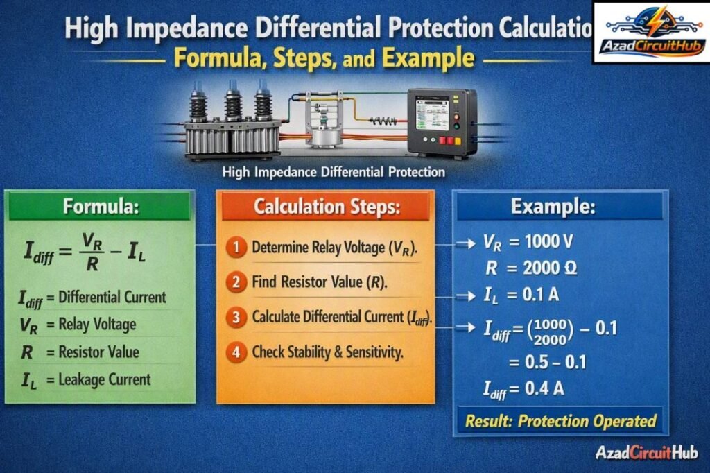
Table of Contents
Table of Contents
What Is High Impedance Differential Protection?
High impedance differential protection is a current balance protection scheme in which the secondary windings of CTs are connected in parallel and the protection relay has relatively high impedance.
Under normal load or an external fault, the CT secondary currents should balance. Ideally, little or no current flows through the relay. During an internal fault, the current balance is disturbed and sufficient voltage develops across the relay circuit to operate the protection.
The scheme normally includes a stabilizing resistor. This resistor increases the circuit impedance and helps prevent the relay from operating when one CT approaches saturation during a severe external fault.
The basic principle can be summarized as:
- CT secondary currents balance during normal conditions.
- An external fault should not produce enough voltage to operate the relay.
- An internal fault creates spill current.
- The resulting voltage must exceed the relay operating threshold.
- The stabilizing resistor provides security against CT saturation.
For engineers working with protection settings, a Differential Protection Relay Setting Calculator can also help verify related differential protection parameters before finalizing relay settings.
Why Is the Stabilizing Resistor Important?
The stabilizing resistor is one of the most important parts of a high impedance scheme. During a high external fault, one CT may saturate before the others. This can create a differential current even though the fault is outside the protected zone.
Without adequate stabilization, the relay could trip unnecessarily.
The resistor raises the voltage required to drive current through the relay circuit. This improves stability by limiting the current flowing through the relay during CT saturation.
The design therefore has two competing requirements:
- The voltage must remain below the relay operating voltage during external faults.
- The voltage must be high enough to operate the relay for internal faults.
This balance is central to High Impedance Differential Protection Calculation.
High Impedance Differential Protection Formula
A commonly used stability calculation begins with the maximum through-fault current and CT secondary circuit resistance.
The approximate stability voltage can be calculated as:
Vst = If × (Rct + Rlead)
Where:
| Symbol | Meaning |
|---|---|
| Vst | Required stabilizing voltage |
| If | Maximum external fault current referred to CT secondary |
| Rct | CT secondary winding resistance |
| Rlead | Resistance of the longest CT lead loop |
In a practical design, the relay burden and other circuit resistances may also need to be considered.
The stabilizing resistor can then be estimated from:
Rstab = (Vst / Irelay) − Rrelay
Where:
- Rstab = stabilizing resistance
- Vst = required stabilizing voltage
- Irelay = relay operating current
- Rrelay = relay internal resistance
The exact formula depends on the protection relay manufacturer’s application method, so the manufacturer’s technical documentation should be checked before commissioning.
Step-by-Step Calculation Example
Consider a busbar protection system with the following values:
| Input | Value |
|---|---|
| CT ratio | 2000/1 A |
| Maximum through-fault current | 20 kA |
| CT secondary resistance | 4 Ω |
| CT lead resistance | 1 Ω |
| Relay operating current | 0.05 A |
| Relay resistance | 1 Ω |
Step 1: Convert Fault Current to CT Secondary
The CT ratio is:
2000/1 = 2000
Therefore:
If = 20,000 / 2000
If = 10 A
The maximum external fault produces 10 A on the CT secondary side.
Step 2: Calculate CT Circuit Resistance
Assuming the CT resistance and lead resistance are included:
Rtotal = Rct + Rlead
Rtotal = 4 + 1
Rtotal = 5 Ω
Step 3: Calculate Stabilizing Voltage
Using:
Vst = If × Rtotal
Vst = 10 × 5
Vst = 50 V
Therefore, the calculated stability voltage is approximately 50 V.
Step 4: Estimate Stabilizing Resistance
Using the simplified relationship:
Rstab = (Vst / Irelay) − Rrelay
Rstab = (50 / 0.05) − 1
Rstab = 999 Ω
A practical standard resistor value would then be selected after checking the relay manufacturer’s requirements, resistor power rating, CT performance, and actual wiring resistance.
This example demonstrates why High Impedance Differential Protection Calculation cannot be based only on the relay pickup current. CT characteristics and wiring resistance have a major effect on scheme stability.
CT Saturation and Stability
CT saturation is a key concern in high impedance differential protection. During a large external fault, the primary current can be several times the normal system current. The CT must reproduce the secondary current accurately enough to maintain current balance.
If one CT saturates while another remains unsaturated, a spill current can flow through the relay circuit.
Important CT parameters include:
- CT ratio
- Knee-point voltage
- CT secondary resistance
- Excitation current
- Accuracy class
- Burden
- Maximum through-fault current
For high impedance schemes, CTs are often selected with matching characteristics and a sufficiently high knee-point voltage.
| CT parameter | Why it matters |
|---|---|
| Knee-point voltage | Indicates CT excitation performance |
| Secondary resistance | Affects stability voltage |
| CT ratio | Determines secondary fault current |
| Excitation current | Influences differential current |
| Accuracy class | Indicates measurement performance |
| Burden | Affects CT voltage requirement |
Knee-Point Voltage Requirement
The CT knee-point voltage is particularly important in a high impedance scheme.
A common engineering requirement is that the CT knee-point voltage should exceed the calculated stabilizing voltage by an appropriate safety margin.
In simplified form:
Vknee > Vst
However, actual specifications often require a higher margin based on the protection design and applicable standard.
For example, if the calculated stability voltage is 50 V, selecting a CT with a knee-point voltage of only 55 V may provide little practical margin. A substantially higher knee-point voltage may be selected depending on the project design.
The CT manufacturer should provide the excitation curve and knee-point data used for verification.
Internal Fault Operation
For an internal fault, CT secondary currents no longer balance because the fault is inside the protected zone.
The resulting spill current produces a voltage across the high impedance circuit.
The relay must receive sufficient voltage or current to exceed its operating threshold.
A simplified operating condition can be expressed as:
Vfault > Voperate
Where Vfault is the voltage produced during the internal fault and Voperate is the relay operating voltage.
The final protection design must verify both sensitivity and stability. A setting that is highly sensitive but unstable is not acceptable, while a highly stable scheme that cannot detect the minimum internal fault is also unsuitable.
For a broader review of differential relay settings and calculations, see the Differential Protection Relay Setting Calculator, which can be used as a useful reference when checking differential protection parameters.
High Impedance vs Low Impedance Differential Protection
Both protection methods use the differential principle, but their circuit arrangements and setting philosophies are different.
| Feature | High impedance | Low impedance |
|---|---|---|
| Relay impedance | High | Relatively low |
| Stabilizing resistor | Normally required | Usually not required in the same manner |
| CT connection | Parallel | Numerical/current input based |
| CT matching | Very important | More flexible |
| CT saturation concern | Significant | Managed through relay algorithms |
| Typical application | Busbar and restricted earth fault | Transformer and modern numerical protection |
| Setting method | Voltage-based | Current/percentage restraint-based |
High impedance protection remains attractive for applications where a simple, fast, and dependable scheme is required.
Common Applications
High impedance differential schemes are particularly common in:
Busbar Protection
Busbar faults can produce extremely high fault currents. Fast clearance is essential because a busbar fault can affect several feeders simultaneously.
Restricted Earth Fault Protection
High impedance schemes are also used for restricted earth fault (REF) protection on transformer and generator windings. The protection zone is limited to the area between the CTs.
Generator Protection
Certain generator stator earth-fault applications can use high impedance arrangements where the CT configuration and system grounding method are suitable.
Transformer Protection
High impedance REF protection can provide sensitive earth-fault detection in transformer windings, complementing main transformer differential protection.
Practical Design Checks
Before applying the calculated settings, engineers should verify the complete secondary circuit rather than relying on a single formula.
Use this checklist:
- Confirm the CT ratio and polarity.
- Determine the maximum external fault current.
- Convert the fault current to CT secondary current.
- Measure or calculate the complete CT lead resistance.
- Confirm CT winding resistance.
- Calculate the required stability voltage.
- Check the relay burden and pickup characteristics.
- Select the stabilizing resistor.
- Verify CT knee-point voltage.
- Check the resistor’s thermal and short-time rating.
- Confirm CT polarity and wiring.
- Perform secondary injection and stability testing.
These checks help identify errors before the protection system is placed in service.
Common Calculation Mistakes
Several errors can produce incorrect protection settings.
Using Primary Current Directly
The fault current must be converted to CT secondary current before it is used in the secondary circuit calculation.
Ignoring Lead Resistance
Long CT leads can have significant resistance. Omitting this value can result in an incorrect stability voltage.
Selecting CTs Without Checking Knee Point
A CT ratio alone does not confirm suitability for a high impedance protection scheme.
Ignoring Relay Burden
The relay’s internal resistance contributes to the total secondary circuit impedance and should be included where required by the design method.
Treating the Resistor as a Standalone Setting
The stabilizing resistor is part of the complete protection circuit. CT performance, wiring, relay characteristics, and fault levels must be considered together.
Testing High Impedance Differential Protection
Testing should verify both stability and operation.
During a stability test, the test equipment simulates an external fault condition. The protection circuit should remain stable even when the expected fault current is represented.
An operation test then confirms that the relay responds correctly to an internal-fault condition.
Typical commissioning checks include:
| Test | Purpose |
|---|---|
| CT ratio test | Confirm transformation ratio |
| Polarity test | Confirm correct CT connections |
| Insulation test | Check wiring insulation |
| Secondary injection | Verify relay operation |
| Stability test | Confirm external-fault security |
| Pickup test | Verify operating threshold |
| Trip test | Confirm complete trip circuit |
Key Takeaways
High impedance differential protection provides a fast and stable method for protecting defined electrical zones. Its performance depends heavily on CT selection, CT saturation behavior, secondary resistance, lead resistance, relay characteristics, and stabilizing resistance.
A sound High Impedance Differential Protection Calculation should always check both external-fault stability and internal-fault sensitivity. The calculated stabilizing voltage is a starting point, not the only design parameter.
For engineers reviewing relay settings across different differential protection applications, the Differential Protection Relay Setting Calculator provides a convenient starting point for related setting calculations.
FAQs
1. What is high impedance differential protection?
High impedance differential protection is a protection method that uses CTs connected in parallel with a high impedance relay circuit. A stabilizing resistor helps prevent unwanted operation during heavy external faults caused by CT saturation.
2. What is the purpose of the stabilizing resistor?
The stabilizing resistor increases the impedance of the relay circuit. This raises the voltage needed to operate the relay and improves security during external or through-fault conditions.
3. Why is CT knee-point voltage important?
The CT knee-point voltage indicates the point at which a small increase in secondary voltage causes a large increase in excitation current. High impedance schemes generally require CTs with sufficient knee-point voltage to remain stable during severe external faults.
4. Where is high impedance differential protection commonly used?
It is commonly used for busbar protection and restricted earth fault protection. It can also be applied to selected generator and transformer protection schemes where the CT arrangement and system requirements are appropriate.
5. Is high impedance protection better than low impedance differential protection?
Neither method is universally better. High impedance protection can offer simple and fast operation with strong external-fault stability, while low impedance numerical protection provides greater flexibility and can accommodate more advanced protection functions. The appropriate choice depends on the system and protection requirements.
Follow Us on Social:
Subscribe our Newsletter on Electrical Insights for latest updates from Azad Circuit Hub
#HighImpedanceDifferentialProtection, #DifferentialProtection, #ProtectionRelay, #CTProtection, #RelaySettings, #PowerSystemProtection, #ElectricalEngineering, #CurrentTransformer, #FaultProtection, #TransformerProtection
