
Differential Relay in Transformer: Working, Protection, Types, and Settings
A transformer is one of the most important and expensive assets in an electrical power system. A fault inside its windings, terminals, or internal connections can cause severe damage if it is not cleared quickly. This is where a differential protection scheme becomes essential.
A Differential Relay in Transformer compares the current entering the transformer with the current leaving it. Under normal conditions, these currents are balanced after accounting for the transformer ratio and phase shift. When an internal fault occurs, the balance is disturbed, and the relay sends a trip command to the associated circuit breakers.
Quick Overview
| Parameter | Details |
|---|---|
| Main purpose | Protection against internal transformer faults |
| Protection principle | Current differential protection |
| Common relay | Percentage or biased differential relay |
| Protected zone | Between the CTs installed on transformer sides |
| Typical faults detected | Phase-to-phase, phase-to-earth, winding faults |
| Main input | CT secondary currents |
| Modern relay type | Numerical differential relay |
| Important settings | Pickup, bias, slope, harmonic restraint |
| Standard reference | IEC 60255 and applicable utility standards |
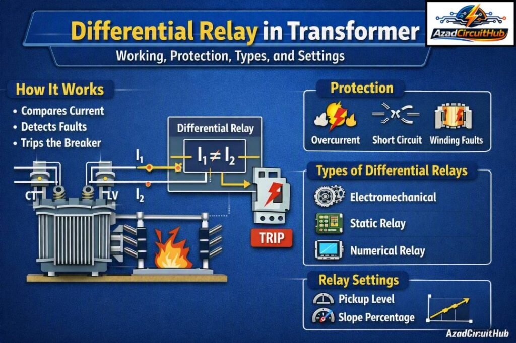
Table of Contents
Table of Contents
What Is Differential Relay in Transformer?
A Differential Relay in Transformer is a protective device that operates when the current entering and leaving the protected transformer zone differs beyond a predefined limit.
The basic principle is based on Kirchhoff’s Current Law. For a healthy transformer, the current entering the protected zone should approximately equal the current leaving it when the currents are correctly referred to the same voltage level.
The relay calculates the difference between the compensated currents:
Differential Current = |I₁ – I₂|
Here, I₁ and I₂ are the compensated currents measured by current transformers on the high-voltage and low-voltage sides.
A small difference can occur because of CT errors, transformer losses, tap changer position, or measurement tolerances. Therefore, the relay does not normally trip for every small current mismatch.
How Does Differential Transformer Protection Work?
Current transformers are installed on both sides of the transformer. Their secondary currents are connected to the differential relay.
The relay compares the two current signals after applying the required ratio, phase, and vector-group compensation. In older installations, CT connections were often arranged to compensate for transformer phase displacement. Modern numerical relays generally perform this compensation electronically.
During normal operation or an external fault, the compensated currents remain sufficiently balanced.
During an internal fault, current flows into the fault location from one or more sides of the transformer. The resulting differential current becomes high enough to operate the relay.
| Operating condition | Differential current | Relay response |
|---|---|---|
| Normal load | Very low | No trip |
| Transformer energization | May be high | Harmonic restraint/blocking |
| External fault | Normally low after compensation | No trip |
| Internal winding fault | High | Trip |
| Internal earth fault | High or moderate | Trip depending on fault location |
| CT saturation | False differential current possible | Bias/restraint improves security |
Protected Zone of a Transformer Differential Relay
The protected zone is the area between the CTs used by the differential protection scheme. This concept is important when troubleshooting a transformer trip.
If a fault occurs inside the CT boundaries, the relay should normally detect it. If the fault occurs outside the CT boundaries, it is considered an external fault and the differential relay should remain stable.
For example, CTs may be installed on the transformer HV and LV sides. The transformer windings and internal connections between those CT locations form the primary differential protection zone.
This arrangement provides fast protection because the relay does not need to wait for downstream protection to clear an internal transformer fault.
Why Bias Is Used in Transformer Differential Protection
A simple differential relay can produce unwanted trips during heavy external faults because CTs may not reproduce primary current perfectly.
One CT may saturate earlier than another. This creates an apparent current difference even though there is no internal fault.
A percentage-biased differential relay solves much of this problem. Its operating threshold increases as the through-fault current increases.
This allows the protection to remain sensitive during low-current internal faults while maintaining stability during high-current external faults.
For engineers working with protection coordination, understanding the relay slope, restraint current, CT performance, and fault level is essential.
For a practical guide to selecting relay pickup, bias, and other protection parameters, see differential protection relay setting calculation before finalizing transformer protection settings.
Main Types of Transformer Differential Relays
Transformer differential protection has developed from electromechanical relays to sophisticated numerical protection systems.
Percentage Differential Relay
Percentage differential relays use a restraining quantity along with differential current. They provide better stability during external faults than basic differential relays.
Biased Differential Relay
A biased relay introduces one or more slopes into its operating characteristic. The bias increases the operating threshold as through current rises.
Numerical Differential Relay
Modern numerical relays use digital signal processing to measure and compare transformer currents. They can compensate for vector group, CT ratio, phase displacement, and tap position.
They can also provide event records, fault oscillography, communication, self-monitoring, and programmable logic.
High-Impedance Differential Protection
High-impedance schemes are commonly associated with busbar and certain restricted earth-fault applications. They require careful CT matching and stabilization calculations.
Important Transformer Differential Relay Settings
Correct settings are critical for both sensitivity and security. The exact values depend on transformer rating, CT ratios, system fault levels, vector group, grounding arrangement, and relay manufacturer.
| Setting | Purpose |
|---|---|
| Differential pickup | Defines minimum operating differential current |
| Bias/slope | Improves stability during external faults |
| High-set differential | Provides fast operation for severe internal faults |
| Harmonic restraint | Prevents unwanted operation during magnetizing inrush |
| Second harmonic restraint | Commonly used for inrush detection |
| Fifth harmonic restraint | Can help identify overexcitation |
| CT ratio compensation | Matches current signals from different voltage levels |
| Vector compensation | Corrects transformer phase displacement |
| Zero-sequence compensation | Used where required by the protection scheme |
Transformer Inrush and Differential Protection
Transformer magnetizing inrush is one of the biggest considerations when setting differential protection.
When a transformer is energized, the magnetizing current can become several times higher than normal full-load current. Although this current enters through the transformer, it does not represent an internal fault.
Without suitable restraint or blocking logic, the relay could interpret the inrush current as a differential fault.
Modern numerical relays commonly analyze harmonic content to distinguish magnetizing inrush from internal faults. Second-harmonic restraint has traditionally been widely used for this purpose.
Differential Protection During External Faults
An external short circuit can produce extremely high currents through a transformer. CT saturation can then create unequal secondary currents.
Suppose the primary currents are equal from the protection system’s perspective, but one CT saturates. The relay may see a false differential current.
The percentage bias characteristic provides additional restraint under these conditions. CT selection, CT class, knee-point voltage, lead resistance, and burden should also be reviewed during protection design.
Common Transformer Faults Detected
A properly designed transformer differential scheme can detect many serious internal faults.
These include:
- Phase-to-phase winding faults
- Phase-to-earth faults
- Winding short circuits
- Inter-turn faults, depending on fault severity and location
- Internal bushing faults within the protected zone
- Faults in internal transformer connections
- Severe insulation failures
Very low-level inter-turn faults can sometimes produce insufficient differential current, particularly when only a small portion of the winding is involved. Additional protection such as Buchholz, restricted earth fault, overcurrent, and temperature protection may therefore be required.
Differential Relay vs Overcurrent Relay
Both protections are important, but they work on different principles.
| Feature | Differential protection | Overcurrent protection |
|---|---|---|
| Main principle | Compares currents | Measures current magnitude |
| Primary application | Internal transformer faults | Backup and external faults |
| Speed | Very fast | Depends on time setting |
| Selectivity | High within protected zone | Depends on coordination |
| CTs | Usually required on multiple sides | Usually required on protected circuit |
| Typical role | Main transformer protection | Backup protection |
For detailed calculations involving CT ratios, restraint current, pickup, and relay slope, use differential protection relay setting calculation as a practical reference alongside the relay manufacturer’s manual.
Key Factors When Setting Differential Protection
Before commissioning a transformer differential relay, engineers should verify several parameters.
First, confirm the transformer MVA rating and voltage ratio. Next, check the CT ratios and CT accuracy classes on every protected side.
The transformer vector group must also be entered correctly into a numerical relay. Incorrect phase compensation can create a permanent differential current and may cause nuisance operation.
Tap changer range is another important factor. On-load tap changes alter the transformer ratio, so the relay should have sufficient tolerance or tap compensation.
Finally, check the protection characteristic against the maximum external short-circuit current and expected CT saturation.
Testing and Commissioning
Testing should be completed before putting transformer differential protection into service.
Important checks include:
- Verify CT polarity.
- Confirm CT ratios.
- Check phase sequence.
- Verify transformer vector-group compensation.
- Confirm relay input wiring.
- Test differential pickup.
- Test bias and slope characteristics.
- Verify harmonic restraint.
- Perform trip circuit testing.
- Check breaker trip commands and alarms.
Secondary injection testing can verify relay characteristics, while primary injection or system-based testing can provide additional confirmation of the complete protection scheme.
Advantages of Transformer Differential Protection
The main advantage is fast and selective fault clearing. Because the relay focuses on the zone between the CTs, it can identify internal transformer faults without unnecessarily disconnecting healthy parts of the electrical network.
Other advantages include high sensitivity, reliable fault discrimination, programmable protection functions, event recording, communication capabilities, and integration with modern substation automation systems.
For engineers preparing a complete transformer protection study, differential protection relay setting calculation can also help organize the key calculations before relay commissioning.
FAQs
1. What is the main purpose of transformer differential protection?
Its main purpose is to detect internal transformer faults quickly by comparing the currents entering and leaving the protected transformer zone.
2. Why does a transformer differential relay not trip during normal load?
The relay compensates for transformer ratio and phase displacement. Under normal conditions, the compensated currents are nearly equal, so the differential current remains below the operating threshold.
3. Why is bias used in differential protection?
Bias improves relay stability during heavy external faults. It helps prevent unwanted tripping caused by CT errors and saturation.
4. Can differential protection detect an earth fault?
Yes. It can detect earth faults within the protected zone when the resulting current is sufficient for the relay to operate. Restricted earth fault protection may provide additional sensitivity for certain transformer applications.
5. Why does transformer inrush not normally trip the differential relay?
Magnetizing inrush has characteristic harmonic content. Modern numerical relays use harmonic restraint or blocking functions to distinguish inrush from many internal fault conditions.
Conclusion
A Differential Relay in Transformer provides fast and selective protection against faults within the transformer’s defined differential zone. Its effectiveness depends on correct CT selection, polarity, ratio matching, vector-group compensation, bias characteristics, and inrush restraint.
Modern numerical relays have made transformer differential protection more flexible by combining accurate current comparison with advanced fault recording, communication, and programmable logic.
However, relay settings should never be selected from generic values alone. Transformer ratings, system fault levels, CT characteristics, grounding, tap range, and the manufacturer’s protection algorithm must all be considered. Proper calculation, testing, and commissioning are essential for a dependable transformer protection system.
Get new guides in your feed. Follow Electrical Insights on LinkedIn for new electrical standards guides, calculators and design tips from Azad Circuit Hub.
#DifferentialRelay, #TransformerProtection, #TransformerRelay, #DifferentialProtection, #PowerSystemProtection, #ElectricalProtection, #TransformerFaults, #ProtectionRelay, #ElectricalEngineering, #RelaySettings
