
What Is Contact Resistance? (Definition & Fundamentals Guide)
| Quick Answer | Details |
|---|---|
| What is contact resistance? | It is the electrical resistance that occurs where two conductive surfaces meet. |
| Unit of measurement | Ohms (Ω), usually measured in milliohms (mΩ) for electrical contacts |
| Main cause | Imperfect contact surfaces, oxidation, contamination, pressure, and surface roughness |
| Common testing method | Four-wire Kelvin resistance measurement |
| Typical applications | Circuit breakers, switches, relays, connectors, busbars, contactors, and terminals |
| Key concern | Excessive resistance can cause voltage drop, heating, and equipment failure |
What Is Contact Resistance?
What Is Contact Resistance? It refers to the small electrical resistance present at the interface between two conducting surfaces. Even when two metal surfaces appear to touch completely, the actual contact area is much smaller than the visible surface area.
Microscopic surface roughness creates tiny points where current can pass from one conductor to another. These small conductive paths are called contact spots or asperities. Because current is forced through these limited areas, a measurable resistance develops.
In a new, clean, properly tightened electrical connection, this resistance is normally very low. However, corrosion, oxidation, loose connections, dirt, mechanical wear, and inadequate contact pressure can increase it.
This makes contact resistance an important parameter in electrical maintenance and power system testing.
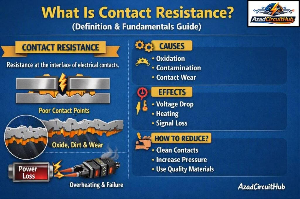
Table of Contents
Table of Contents
Why Does Contact Resistance Occur?
The surfaces of electrical contacts are never perfectly smooth. Under a microscope, even polished copper, aluminum, silver, or other conductive materials have peaks and valleys.
When two surfaces are pressed together, current does not flow across the entire apparent contact area. Instead, it concentrates through microscopic contact points.
This creates what is commonly called constriction resistance.
Other factors can add to the resistance, including:
- Oxide and corrosion layers
- Dust and contamination
- Surface roughness
- Insufficient contact pressure
- Mechanical wear
- Improper torque
- Contact material
- Temperature
- Repeated switching operations
| Factor | Effect on Resistance |
|---|---|
| High contact pressure | Usually reduces resistance |
| Oxidation | Increases resistance |
| Corrosion | Increases resistance |
| Contamination | Increases resistance |
| Smooth, clean surfaces | Usually reduce resistance |
| Loose terminal | Can significantly increase resistance |
| High temperature | Can change resistance and accelerate degradation |
| Mechanical wear | May increase resistance over time |
Contact Resistance vs Conductor Resistance
Contact resistance should not be confused with the normal resistance of a conductor.
A copper cable has resistance along its length. A connection between two cables, however, can introduce additional resistance at the interface.
For example, a properly installed bolted connection may have only a very small resistance. If the connection becomes loose or develops corrosion, its resistance can increase while the cable itself remains in good condition.
| Characteristic | Conductor Resistance | Contact Resistance |
|---|---|---|
| Location | Along the conductor | At a connection or interface |
| Main factors | Length, area, material, temperature | Pressure, surface condition, contamination |
| Typical value | Depends on conductor size and length | Usually very low |
| Common test | Low-resistance ohmmeter | Micro-ohmmeter |
| Typical problem | Undersized or damaged conductor | Loose, oxidized, worn, or contaminated contact |
Why Low Contact Resistance Matters
A low-resistance electrical connection allows current to flow efficiently. Excessive resistance can create several problems.
The most important issue is heat generation. The power dissipated at a connection can be calculated using:
P = I²R
where:
- P = power dissipated as heat in watts
- I = current in amperes
- R = contact resistance in ohms
Consider a connection carrying 500 A with a resistance of 100 micro-ohms:
P = 500² × 0.0001
P = 25 W
Twenty-five watts generated at a small connection point can produce significant localized heating.
As temperature rises, the connection may deteriorate further. This can create a dangerous cycle in which increased resistance causes more heating, and heating contributes to further degradation.
What Causes High Contact Resistance?
Several installation and operating conditions can cause an electrical contact to develop excessive resistance.
Loose Connections
Insufficient tightening reduces contact pressure and limits the number of effective conductive contact spots.
Corrosion and Oxidation
Metal surfaces can develop oxide or corrosion layers over time. Some oxide layers have much higher electrical resistance than the base metal.
Contamination
Oil, dust, moisture, dirt, and other contaminants can interfere with metal-to-metal contact.
Mechanical Wear
Switchgear, contactors, circuit breakers, and relays can experience mechanical and electrical wear during operation.
Improper Installation
Incorrect torque, damaged contact surfaces, poor alignment, or unsuitable hardware can all contribute to increased resistance.
How Is Contact Resistance Measured?
A low-resistance ohmmeter, often called a micro-ohmmeter or DLRO (digital low-resistance ohmmeter), is commonly used.
For very low resistance values, ordinary multimeters are often unsuitable. Test lead resistance and connection resistance can be much larger than the resistance being measured.
A four-wire Kelvin measurement solves much of this problem.
| Test Method | Accuracy for Low Resistance | Typical Use |
|---|---|---|
| Standard two-wire multimeter | Low | Basic resistance checks |
| Four-wire Kelvin test | High | Low-resistance contact testing |
| Micro-ohmmeter | High | Switchgear, breakers, busbars |
| DLRO | High | Electrical maintenance and commissioning |
Four-Wire Kelvin Measurement Explained
A four-wire resistance test uses two current leads and two voltage-sensing leads.
The test instrument sends a known current through the connection using the current leads. Separate sensing leads measure the voltage drop across the contact.
Resistance is then calculated using Ohm’s law:
R = V / I
Because the voltage measurement circuit draws very little current, the resistance of the voltage leads has minimal influence on the result.
This method is particularly useful when measuring values in the micro-ohm or milliohm range.
Where Is Contact Resistance Tested?
Contact resistance testing is widely used in power distribution and industrial electrical systems.
| Equipment | Reason for Testing |
|---|---|
| Circuit breakers | Detect deteriorated main contacts |
| Disconnect switches | Verify contact condition |
| Contactors | Identify worn or damaged contacts |
| Relays | Check switching contacts |
| Busbar joints | Detect poor bolted connections |
| Cable lugs | Verify connection quality |
| Switchgear | Confirm low-resistance current paths |
| High-current connectors | Prevent overheating and losses |
For engineers working with switchgear maintenance, knowing the applicable contact resistance test iec standard requirements can help ensure that testing methods and acceptance criteria are selected correctly.
What Is a Good Contact Resistance Value?
There is no single resistance value that applies to every electrical contact. The acceptable result depends on the equipment design, manufacturer specifications, rated current, contact construction, and applicable testing standard.
For this reason, a test result should not be judged only by whether it appears to be “low.”
The better approach is to compare the measured value with the manufacturer’s recommended limit and previous test results.
| Test Result | Possible Interpretation |
|---|---|
| Very low and stable | Generally indicates a good connection |
| Slightly higher than previous test | Requires investigation |
| Significant increase | Possible deterioration |
| Large difference between phases | Possible contact or connection problem |
| Rapid increase over time | Strong indication of degradation |
Contact Resistance Testing Procedure
A typical low-resistance test involves several practical steps.
1. Isolate the Equipment
The equipment must be safely isolated, de-energized, and properly grounded according to the applicable safety procedure.
2. Inspect the Connection
Check for corrosion, overheating, discoloration, loose hardware, damaged contacts, or other visible defects.
3. Connect the Test Instrument
Attach the current and voltage leads correctly using the four-wire measurement arrangement.
4. Apply the Test Current
The micro-ohmmeter injects a controlled DC test current through the contact.
5. Measure Voltage Drop
The instrument measures the voltage drop across the connection and calculates resistance.
6. Compare Results
Compare the reading with the manufacturer’s specification, previous measurements, and other similar phases or poles.
7. Record the Results
Document the resistance value, test current, equipment identification, temperature, test date, and any observations.
For detailed acceptance criteria and testing procedures, engineers should review the applicable contact resistance test iec standard together with the equipment manufacturer’s instructions.
Contact Resistance Testing Best Practices
Good testing depends on more than simply connecting a meter and recording a number.
Use these practices:
- Clean suitable test points before measurement.
- Use a calibrated low-resistance tester.
- Keep test lead connections secure.
- Follow the equipment manufacturer’s test procedure.
- Use the recommended test current.
- Record readings for each phase or pole.
- Compare results with historical data.
- Investigate unusual phase-to-phase differences.
- Avoid interpreting one reading without considering equipment specifications.
- Follow electrical safety and isolation procedures.
Common Signs of Excessive Contact Resistance
High contact resistance may not be immediately visible. However, several warning signs can indicate a developing problem.
These include:
- Localized overheating
- Discoloration around terminals
- Burning smell
- Voltage drop under load
- Intermittent operation
- Pitted or damaged contacts
- Increased temperature at a joint
- Unequal resistance between phases
- Repeated equipment failures
Thermal imaging can also be useful during energized inspections because a high-resistance connection may appear as a localized hot spot. Thermal inspection, however, does not replace a proper low-resistance test.
Contact Resistance in Circuit Breakers
Circuit breakers are one of the most common applications for contact resistance testing.
When a breaker is closed, current passes through its main contacts. Those contacts must provide a low-resistance path under normal load conditions.
A high resistance value can indicate contact wear, contamination, inadequate pressure, mechanical problems, or damage.
Regular testing helps maintenance teams identify deterioration before it develops into serious overheating or an unexpected outage.
Following the correct contact resistance test iec standard for the equipment type can make test records more useful for commissioning and preventive maintenance.
Frequently Asked Questions
1. What is contact resistance in simple terms?
It is the small amount of resistance found where two electrical conductors or metal contacts meet. It occurs because real surfaces touch at microscopic points rather than across their entire apparent area.
2. How is contact resistance measured?
It is commonly measured with a micro-ohmmeter or DLRO using a four-wire Kelvin test. The instrument applies a known current and measures the voltage drop across the connection.
3. Why is contact resistance important?
High contact resistance can cause voltage drop, localized heating, energy losses, and equipment deterioration. In high-current systems, even a very small resistance can generate significant heat.
4. Can a multimeter measure contact resistance?
A standard multimeter may measure ordinary resistance, but it is generally not suitable for accurate micro-ohm measurements. Test lead resistance can significantly affect the result, so a four-wire low-resistance tester is preferred.
5. What causes contact resistance to increase?
Common causes include loose connections, oxidation, corrosion, contamination, mechanical wear, damaged contacts, insufficient pressure, poor installation, and thermal deterioration.
Final Takeaway
Understanding What Is Contact Resistance is important for anyone involved in electrical installation, testing, commissioning, or maintenance. Although the resistance of a good electrical connection is very small, even a few micro-ohms can become important when high current is involved.
Regular low-resistance testing helps identify deteriorating connections, worn switchgear contacts, poor busbar joints, and other developing electrical problems. Combining micro-ohm testing with visual inspection, thermal inspection, manufacturer limits, and historical test data provides a much clearer picture of connection health.
For engineers and technicians, using the correct testing method and following the applicable contact resistance test iec standard is essential for obtaining reliable and meaningful results.
Get new guides in your feed. Follow Electrical Insights on LinkedIn for new electrical standards guides, calculators and design tips from Azad Circuit Hub.
#ContactResistance, #ElectricalEngineering, #ElectricalTesting, #ResistanceTesting, #ElectricalContacts, #CircuitTesting, #ElectricalSafety, #ContactResistanceTesting, #PowerSystems, #ElectricalMaintenance
