
Electrical Earthing Types & Methods: Complete Guide to Earthing Systems
Electrical earthing is one of the most important safety measures in an electrical installation. It provides a controlled path for fault current to flow into the ground and helps keep exposed metal parts near earth potential. A properly designed system can reduce electric shock risk, equipment damage, fire hazards, and dangerous touch voltages.
There are several electrical earthing types used in homes, commercial buildings, substations, industries, transmission networks, and electronic systems. The suitable arrangement depends on the voltage level, soil conditions, fault current, installation type, and applicable electrical standard.
Quick Comparison of Electrical Earthing Types
The following table gives a quick overview of common earthing arrangements and their typical applications.
| Earthing Type | Main Feature | Typical Application |
|---|---|---|
| Plate Earthing | Earth electrode is a metal plate | Buildings and industrial installations |
| Pipe Earthing | Galvanized or copper pipe electrode | Residential and commercial systems |
| Rod Earthing | Metal rod driven into soil | Small installations and rocky locations |
| Strip Earthing | Metal strip buried horizontally | Large buildings and substations |
| Chemical Earthing | Electrode with conductive backfill | High-resistance soil |
| Grid Earthing | Interconnected buried conductors | Substations and power plants |
| Mat Earthing | Large interconnected earth network | High-voltage substations |
| Neutral Earthing | System neutral connected to earth | Power generation and distribution |
| Equipment Earthing | Metal equipment bonded to earth | Electrical safety |
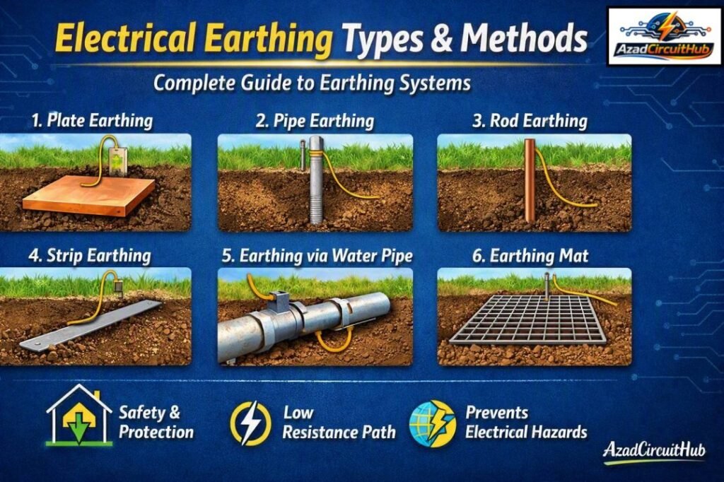
Table of Contents
Table of Contents
What Is Electrical Earthing?
Electrical earthing is the intentional connection of electrical equipment, structures, or a power system to the earth through a suitable conductor and earth electrode.
The basic purpose is to provide a low-impedance path for fault current. If insulation fails and a live conductor touches a metal enclosure, the earthing conductor provides a path that allows protective devices such as circuit breakers or fuses to operate.
A typical earthing system includes:
- Earth electrode
- Earthing conductor
- Protective bonding conductor
- Main earthing terminal
- Equipment bonding connections
- Grounding grid or buried conductor where required
The terms earthing and grounding are often used interchangeably. In many standards, “grounding” is more common in North America, while “earthing” is widely used in IEC-based systems and many other countries.
Types of Earthing in Electrical Systems
The main types of earthing can be divided into equipment earthing and system earthing.
| Category | Purpose | Example |
|---|---|---|
| Equipment Earthing | Protects people from exposed conductive parts | Motor frame connected to earth |
| System Earthing | Controls the electrical potential of a power system | Transformer neutral grounded |
| Protective Earthing | Provides protection against electric shock | Distribution board enclosure |
| Functional Earthing | Provides a defined reference for equipment operation | Sensitive electronic equipment |
These electrical earthing types serve different purposes, although a complete installation may use more than one arrangement.
Common Methods of Earthing
The physical method used to establish an earth connection depends mainly on the soil, available space, fault current, installation size, and required earth resistance.
Pipe Earthing
Pipe earthing uses a galvanized steel or copper pipe installed vertically in the ground. It is widely used because it is relatively economical and can provide good contact with surrounding soil.
The electrode dimensions and installation depth should be selected according to the applicable standard and soil conditions rather than relying on one universal size.
Plate Earthing
Plate earthing uses a copper or galvanized steel plate buried in an earth pit. The plate is surrounded by suitable conductive material to improve contact with the soil.
This arrangement requires more excavation than rod earthing and is therefore less convenient where installation space is limited.
Rod Earthing
Rod earthing uses a conductive rod driven into the ground. Multiple rods can be installed and interconnected when one electrode cannot provide the required performance.
Rod electrodes are particularly useful where deep soil layers have lower resistivity.
Strip Earthing
Strip earthing uses a horizontal metal strip or conductor buried below ground. It is useful for larger installations and can be interconnected with other earth electrodes.
Industrial facilities, buildings, and substations may use buried strips as part of a larger grounding network.
Chemical Earthing
Chemical earthing uses an earth electrode together with conductive backfill material designed to maintain a reliable connection with the surrounding soil.
It may be considered where soil resistivity is high, but the choice of electrode and backfill should comply with the applicable standard. Chemical treatment is not a substitute for proper earthing design.
Types of Earthing Systems
Electrical systems also have different earthing arrangements based on how the source, exposed conductive parts, and protective conductors are connected.
IEC 60364 commonly identifies TN, TT, and IT arrangements.
| System | Source Neutral | Equipment Connection | Typical Characteristic |
|---|---|---|---|
| TN-S | Earthed | Separate PE conductor | Neutral and protective conductor remain separate |
| TN-C | Earthed | Combined PEN conductor | Neutral and protective functions are combined |
| TN-C-S | Earthed | Combined then separated | PEN changes to separate PE and N |
| TT | Earthed | Local earth electrode | Installation has its own earth electrode |
| IT | Isolated or impedance connected | Local protective earth | First earth fault current is limited |
The selection of a system earthing arrangement depends on the supply network, local regulations, protection requirements, and installation design.
TNCS Earthing System
A TNCS earthing system (TN-C-S) combines the neutral and protective functions in part of the supply network, then separates them into neutral and protective earth conductors at the service position. This arrangement provides a low-impedance fault path, helping protective devices disconnect quickly during an earth fault.
It is widely used in low-voltage installations where the supply authority provides a combined PEN conductor. When comparing different Electrical Earthing Types, TN-C-S should be assessed for bonding, conductor sizing, and local wiring regulations.
| Feature | TN-C-S System |
|---|---|
| Combined conductor | PEN |
| Separate conductors | N and PE after split |
| Main benefit | Fast fault clearing |
| Key concern | PEN conductor integrity |
For a deeper explanation, installation arrangement, advantages, and safety requirements, see this guide to TNCS earthing system.
What Are the 4 Types of Earthing?
The phrase “four types of earthing” can refer to different classifications depending on the standard or educational source. For physical electrodes, common categories include plate, pipe, rod, and strip earthing.
For power-system neutral treatment, classifications may include solid, resistance, reactance, and resonant grounding.
Therefore, there is no single universal list of four types that applies to every electrical installation.
Power System Earthing
Power system earthing refers to connecting a generator, transformer, or other power-system neutral point to earth.
The main objective is to control fault current and stabilize system voltages during abnormal conditions.
Common neutral grounding methods include:
| Method | Fault Current | Typical Use |
|---|---|---|
| Solid Earthing | High | Low-voltage distribution |
| Resistance Earthing | Limited | Industrial systems |
| Reactance Earthing | Limited | Selected medium-voltage systems |
| Resonant Earthing | Very low under certain faults | Specialized distribution networks |
The grounding method must be coordinated with protection relays, circuit breakers, system voltage, and expected earth-fault current.
Types of Earthing in Transmission Lines
Transmission lines require specialized grounding arrangements because of their high voltage, large fault currents, lightning exposure, and extensive physical length.
Typical arrangements include:
- Tower footing earthing
- Grounding electrodes
- Counterpoise conductors
- Buried earth wires
- Overhead ground wires
- Substation grounding grids
Tower footing resistance is particularly important because poor grounding can increase the risk of dangerous potential rise and lightning-related insulation problems.
Earthing Methods for Buildings
Residential and commercial installations commonly use earth electrodes connected to the main earthing terminal. All required exposed conductive parts are bonded to the protective earthing system.
| Building Area | Typical Earthing Requirement |
|---|---|
| Distribution board | Protective earth connection |
| Metal enclosure | Bonded to PE |
| Water or other metallic services | Bonding where required |
| Motors | Equipment grounding |
| Solar inverter | Protective and functional connections as specified |
| EV charger | Protective earthing and bonding |
| Generator | System and equipment grounding as designed |
The actual arrangement should always follow the applicable electrical code and equipment manufacturer’s instructions.
Earthing Layers and Earth Electrode Installation
Earth electrode performance depends heavily on soil resistivity and moisture. Soil is not electrically uniform, so different layers can have significantly different resistance.
An earth electrode should be installed to reach suitable soil conditions where practical. Increasing electrode depth, using multiple electrodes, or installing an interconnected grounding grid may improve performance.
Simply adding salt or other materials around an electrode is not a reliable substitute for proper engineering.
Electrical Grounding Methods
Electrical grounding methods can be grouped into three broad purposes:
- Protective grounding: protects people from hazardous touch voltage.
- System grounding: establishes the electrical reference of the power system.
- Functional grounding: provides a stable reference needed for particular equipment.
Sensitive electronics may also require carefully designed grounding and bonding to reduce electromagnetic interference, ground loops, and unwanted noise.
How Does Electrical Earthing Work?
When an insulation fault connects a live conductor to an exposed metal enclosure, fault current flows through the protective conductor and grounding network toward the source.
This fault path must have sufficiently low impedance to allow the protective device to disconnect the circuit within the required time.
The basic fault-current path can be represented as:
Faulted equipment → PE conductor → grounding connection → source neutral/ground point → transformer or generator winding → faulted circuit
This is why simply having an earth electrode is not enough. The complete fault-current loop and protective-device operation must be considered.
How to Do Electrical Earthing
A safe earthing installation normally involves:
- Assessing the electrical system and soil conditions.
- Selecting an appropriate electrode arrangement.
- Installing the electrode according to the applicable standard.
- Connecting the protective earthing conductor.
- Bonding required exposed conductive parts.
- Connecting the system grounding point where required.
- Testing continuity and earth resistance or impedance.
- Verifying protective-device operation.
Electrical work should be carried out by a qualified electrician or electrical engineer, especially for service entrances, generators, transformers, industrial systems, and high-voltage installations.
Earthing and Its Types for Solar Systems
Solar PV systems can require both equipment grounding and system grounding depending on the inverter architecture and applicable code.
Metal module frames, mounting structures, inverter enclosures, and other exposed conductive parts may require bonding. DC arrays also require specific grounding and bonding arrangements.
For conductor selection, use the applicable electrical code and manufacturer’s requirements rather than choosing an earth conductor based only on the phase cable size.
For related conductor calculations, an AC cable sizing tool can help determine the phase conductor before the protective earthing conductor is selected according to the relevant standard.
Earthing Systems for Electronics
Electronics earthing has additional requirements because sensitive equipment can be affected by electrical noise and unwanted circulating currents.
Computers, communication equipment, instrumentation, PLC systems, and control panels may need carefully planned protective bonding, functional grounding, cable shielding, and equipotential bonding.
A good design separates the purpose of protective safety grounding from signal-reference requirements while maintaining the connections required by the applicable standards.
Earthing Layers, Soil Resistivity and Earth Resistance
Soil resistivity is one of the most important factors affecting an electrode’s performance.
| Factor | Effect on Earthing |
|---|---|
| Soil resistivity | Lower resistivity generally improves electrode performance |
| Electrode depth | Can reach better soil layers |
| Electrode spacing | Affects mutual resistance |
| Soil moisture | Usually changes soil conductivity |
| Electrode surface area | Larger contact area can reduce resistance |
| Multiple electrodes | Can improve overall grounding performance |
Earth resistance should be measured using an appropriate test method and suitable instrument. A low resistance value alone does not prove that the entire protective system is correctly designed.
Types of Earthing Arrangements
Common electrical earthing arrangements include:
- TN-S
- TN-C
- TN-C-S
- TT
- IT
- Solidly grounded systems
- Resistance-grounded systems
- Reactance-grounded systems
- Resonant-grounded systems
These arrangements should not be confused with physical electrode types such as rods, plates, pipes, and strips.
Earthing vs Grounding
In everyday electrical engineering, earthing and grounding are often treated as equivalent terms. The exact terminology varies by region and standard.
| Term | Common Usage |
|---|---|
| Earthing | Common in IEC and many international systems |
| Grounding | Common in North American electrical practice |
| Protective earth (PE) | Safety connection to exposed conductive parts |
| Grounded conductor | A conductor intentionally connected to ground |
| Grounding electrode | Physical connection between system and earth |
The important issue is not the word used but whether the complete grounding and bonding arrangement meets the applicable requirements.
Earthing System Design Considerations
A reliable earthing system should consider more than the earth electrode alone.
Key design factors include:
- Maximum earth-fault current
- Fault clearing time
- Soil resistivity
- Touch voltage
- Step voltage
- Conductor thermal withstand
- Corrosion
- Mechanical strength
- Electrode spacing
- Lightning protection
- Equipment bonding
- Future expansion
- Local electrical regulations
For substations and high-voltage installations, grounding-grid design may require detailed calculations based on fault current distribution, surface potential, touch voltage, and step voltage.
Frequently Asked Questions
What are the main types of earthing?
Common physical electrode types include pipe, plate, rod, and strip earthing. Electrical systems may also be classified as TN, TT, and IT, while power-system neutral grounding can be solid, resistance, reactance, or resonant.
What is the best earthing method?
There is no single best method for every site. The correct earthing method depends on soil resistivity, fault current, system voltage, installation type, available space, and the requirements of the applicable electrical standard.
What is solid earthing?
Solid earthing, or solid grounding, connects the system neutral directly to earth without intentionally adding resistance or reactance. It allows substantial earth-fault current, which helps protective devices detect and clear faults quickly.
How many types of grounding are there?
The answer depends on the classification. Physical grounding electrodes include rods, pipes, plates, and strips, while system grounding arrangements include TN, TT, and IT. Neutral grounding also has several methods.
How does electrical earthing protect against electric shock?
When a fault energizes a metal enclosure, the protective earthing path carries fault current back toward the source. If the fault loop impedance is sufficiently low, the protective device can disconnect the supply and limit the duration of dangerous touch voltage.
Final Takeaway
Understanding electrical earthing types is essential for designing safe residential, commercial, industrial, solar, and power-system installations. Physical electrode methods such as rod, pipe, plate, and strip earthing establish the connection with soil, while TN, TT, IT, and neutral grounding arrangements describe how the electrical system is referenced and protected.
A properly engineered earthing system must consider soil conditions, fault current, protective devices, conductor sizing, bonding, touch voltage, and applicable electrical standards. Good earthing is not simply about achieving a particular resistance reading; it is about creating a dependable fault-current path and maintaining electrical safety throughout the installation.
Follow Us on Social:
Subscribe our Newsletter on Electrical Insights for latest updates from Azad Circuit Hub
#ElectricalEarthing, #EarthingTypes, #EarthingMethods, #ElectricalGrounding, #EarthingSystem, #ElectricalSafety, #GroundingSystem, #EarthingElectrode, #ElectricalEngineering, #GroundingMethods
