
How to Use Megger Insulation Tester 5000V: Step-by-Step Guide
A 5000V insulation resistance tester is used when ordinary multimeters cannot provide enough test voltage to assess the condition of high-voltage insulation. It is commonly used on motors, generators, transformers, switchgear, cables, and other electrical equipment where insulation resistance needs to be checked before commissioning, maintenance, or troubleshooting.
Learning how to use a Megger insulation tester safely is important because a 5000V test can place a dangerous voltage on the equipment under test. The test should only be performed by a qualified person who understands electrical isolation, discharge procedures, and the manufacturer’s instructions.
5000V Megger Insulation Test: Quick Reference
| Item | Typical Practice |
|---|---|
| Test voltage | 500V to 5000V DC, depending on equipment |
| Main measurement | Insulation resistance in MΩ or GΩ |
| Common applications | Motors, generators, transformers, cables, switchgear |
| Test condition | Equipment isolated and de-energized |
| Test leads | Guard, line, and earth leads where supported |
| Main safety requirement | Lockout/tagout and verify zero voltage |
| After test | Discharge the equipment safely |
| Important readings | Insulation resistance, PI, DAR where applicable |
| Test duration | Commonly 1 minute for a basic IR test |
| Reference standard | Equipment-specific standards and manufacturer limits |
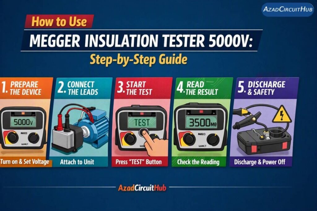
Table of Contents
Table of Contents
What Is a 5000V Megger Insulation Tester?
A Megger insulation tester applies a controlled DC voltage to electrical insulation and measures the small leakage current that flows through it. The instrument then calculates insulation resistance using the relationship between voltage and current.
The basic principle is:
Insulation Resistance = Test Voltage ÷ Leakage Current
For example, if a tester applies 5000V and measures a very small leakage current, the calculated insulation resistance can be several hundred megohms or even several gigohms.
A high resistance generally indicates good insulation, while a low or unstable reading may indicate moisture, contamination, aging, damage, or another insulation problem.
It is important to understand that a high reading alone does not prove that equipment is safe. The test voltage, equipment type, temperature, previous readings, and manufacturer’s requirements all matter.
When Should You Use a 5000V Insulation Tester?
A 5000V insulation tester is normally used on equipment where a higher DC test voltage is appropriate. The correct voltage should never be selected simply because the tester is capable of producing 5000V.
| Equipment | Typical Test Range* | What to Check |
|---|---|---|
| Low-voltage motor | 500–1000V DC | Winding-to-ground insulation |
| LV power cable | 500–1000V DC | Conductor-to-ground and between conductors |
| Medium-voltage cable | 2500–5000V DC or specified value | Insulation condition |
| Generator winding | 500–5000V DC | Winding insulation |
| Transformer | Equipment-specific | Winding-to-ground and winding-to-winding |
| Switchgear | Equipment-specific | Phase-to-ground and phase-to-phase insulation |
*These are general examples, not universal test limits. Always follow the equipment manufacturer’s instructions and applicable testing standard.
How to Use Megger Insulation Tester 5000V Step-by-Step
Before starting, inspect the tester, leads, probes, and equipment. Do not begin the test if there is visible damage or if the isolation status is uncertain.
1. Identify the Equipment and Test Requirement
First determine what you are testing and why.
Check the equipment nameplate, wiring diagram, manufacturer’s manual, maintenance history, and applicable testing procedure. Confirm the recommended insulation resistance test voltage before connecting the instrument.
For example, a motor winding and a medium-voltage cable may require very different test procedures.
Record the equipment identification and ambient conditions before taking measurements.
2. Isolate the Equipment Completely
Turn off the equipment and isolate all possible sources of electrical energy.
This may include:
- Main electrical supply
- Backup generator supply
- UPS supply
- Control circuits
- Capacitor banks
- Stored electrical energy
- Parallel circuits
- Backfeed sources
Apply the appropriate lockout/tagout procedure.
Do not rely only on an open circuit breaker. Verify that the equipment is actually de-energized with an approved voltage detector or meter.
3. Verify Zero Voltage
Before connecting the Megger, confirm that no dangerous voltage remains.
Test the relevant conductors against ground and, where applicable, between conductors.
| Check | Purpose |
|---|---|
| Phase to ground | Confirms conductor is not energized |
| Phase to phase | Detects remaining electrical potential |
| Positive/negative to ground | Important for DC circuits |
| Stored energy | Identifies capacitive or other stored charge |
Only proceed after the isolation has been verified.
4. Disconnect Sensitive Components
A high-voltage insulation test can damage electronic components.
Disconnect equipment such as:
- Variable frequency drives
- PLC input/output modules
- Electronic control boards
- Surge protection devices
- Sensors
- Communication equipment
- Electronic meters
- Capacitors where required by the test procedure
Never assume connected electronics can tolerate 5000V DC.
5. Inspect and Connect the Test Leads
Inspect the leads for damaged insulation, exposed conductors, cracked probes, or loose connections.
A typical insulation tester has connections marked something similar to:
- L or Line
- E or Earth
- G or Guard
The exact arrangement depends on the instrument.
For a basic winding-to-ground test, the Line lead is connected to the conductor or winding under test, while the Earth lead is connected to the equipment frame or ground.
The Guard terminal is useful when surface leakage could affect the measurement.
6. Select the Correct Test Voltage
This is one of the most important steps.
Do not automatically select 5000V just because the instrument is rated for 5kV.
The appropriate test voltage depends on the equipment, insulation system, voltage rating, manufacturer requirements, and applicable testing procedure.
For example, a low-voltage motor may be tested at 500V or 1000V, while some medium-voltage equipment may require a substantially higher test voltage.
7. Start the Insulation Resistance Test
Make sure everyone is clear of the equipment and exposed conductors.
Select the required test voltage and start the test according to the tester’s operating instructions.
During the test, observe the resistance reading.
Initially, the reading may change quickly as the insulation charges. It may then rise and stabilize.
A typical display may show:
| Display | Meaning |
|---|---|
| OL or > maximum | Resistance is above instrument range |
| Low MΩ | Potential insulation problem |
| Increasing resistance | Normal charging/polarization behavior may be occurring |
| Unstable reading | Possible moisture, contamination, connection issue, or external leakage |
| GΩ range | Very high insulation resistance |
Do not touch the equipment or test leads while the test voltage is being applied.
8. Record the 1-Minute Reading
For a basic insulation resistance test, the one-minute value is commonly recorded.
For example:
| Time | Insulation Resistance |
|---|---|
| 15 seconds | 420 MΩ |
| 30 seconds | 610 MΩ |
| 45 seconds | 760 MΩ |
| 60 seconds | 890 MΩ |
The trend can provide useful information in addition to the final value.
However, do not judge insulation condition from a single number without considering the equipment type and historical data.
9. Perform PI or DAR Tests When Required
Many advanced insulation testers can automatically calculate Polarization Index (PI) and Dielectric Absorption Ratio (DAR).
PI is commonly calculated as:
PI = 10-minute insulation resistance ÷ 1-minute insulation resistance
For example:
10-minute reading = 1800 MΩ
1-minute reading = 900 MΩ
PI = 1800 ÷ 900 = 2.0
DAR uses a shorter time interval and is useful for certain applications.
| Test | Typical Measurement |
|---|---|
| IR test | Resistance at a selected time |
| DAR | Ratio of readings at two shorter intervals |
| PI | 10-minute reading ÷ 1-minute reading |
PI and DAR interpretation should follow the relevant equipment standard or manufacturer’s procedure rather than relying on one universal pass/fail number.
10. Stop the Test and Discharge the Equipment
This step is critical.
After the measurement, stop the test and allow the instrument’s discharge function to operate. Capacitive equipment such as long cables and motor windings can retain electrical charge after the test.
Never immediately touch the conductor after applying 5000V DC.
Confirm that the equipment has discharged according to the tester’s instructions. Some testers provide an automatic voltage indication during discharge.
For large equipment, follow the site procedure for additional grounding or discharge.
11. Disconnect the Leads Safely
Only disconnect the test leads after the test voltage has been removed and the equipment has been safely discharged.
Remove the leads using the approved procedure and avoid contact with exposed conductive parts.
Store the tester and leads properly after the test.
How to Interpret Megger Insulation Resistance Readings
There is no single insulation resistance value that can be used as a universal pass/fail limit for every motor, cable, transformer, or generator.
A useful assessment considers:
- Equipment voltage rating
- Insulation class
- Manufacturer specifications
- Equipment temperature
- Test voltage
- Test duration
- Previous test results
- Environmental conditions
- Moisture and contamination
- Equipment age
Historical readings are particularly valuable. A significant downward trend may deserve investigation even when the current value still appears relatively high.
Factors That Affect a 5000V Megger Test
Temperature has a major effect on insulation resistance. In many insulation systems, resistance decreases as temperature increases.
| Factor | Possible Effect |
|---|---|
| High temperature | Can reduce measured resistance |
| Moisture | Can reduce insulation resistance |
| Dirt or contamination | Can increase surface leakage |
| Long cable | Can require longer discharge time |
| Old insulation | May show declining resistance |
| Poor connection | Can produce unreliable readings |
| Incorrect test voltage | Can make comparison difficult |
For meaningful maintenance records, record the temperature and test conditions along with the resistance value.
How to Use Megger BM5200 Insulation Tester 5kV
The Megger BM5200 is a 5 kV insulation resistance tester designed for high-voltage testing of cables, motors, transformers, switchgear, and other electrical equipment. If you are learning How to Use Megger Insulation Tester 5000V, the BM5200 provides a practical example of how a professional 5 kV insulation test is performed.
Megger BM5200 5kV Test Procedure
| Step | What to Do | Important Point |
|---|---|---|
| 1 | Isolate the equipment | Switch off, lock out and tag out the circuit |
| 2 | Verify zero voltage | Use an approved voltage tester before connecting the Megger |
| 3 | Disconnect sensitive equipment | Remove electronic devices, VFDs and control circuits where applicable |
| 4 | Connect test leads | Connect LINE to the conductor under test and EARTH to ground/return |
| 5 | Select test voltage | Select an appropriate voltage, up to 5 kV for suitable equipment |
| 6 | Start the test | Initiate the insulation resistance test and maintain the selected test voltage |
| 7 | Record the result | Note insulation resistance, test voltage and test duration |
| 8 | Discharge the equipment | Allow the tester to discharge the circuit before touching the conductors |
Typical BM5200 5kV Test Applications
| Equipment | Typical Test Voltage* | What to Check |
|---|---|---|
| LV motor | 500–1,000 V | Winding-to-earth insulation |
| LV cable | 500–1,000 V | Conductor-to-earth insulation |
| MV cable | 2.5–5 kV | Insulation condition |
| Transformer | 2.5–5 kV | Winding-to-earth and winding-to-winding |
| Switchgear | 2.5–5 kV | Insulation between isolated sections |
*Test voltage should be selected according to the equipment manufacturer’s instructions and the applicable testing standard—not simply because the BM5200 can produce 5 kV.
For a safe How to Use Megger Insulation Tester 5000V procedure, never connect the instrument to energized equipment. After completing the test, keep the leads connected long enough for the equipment to discharge through the tester, then verify that no dangerous voltage remains. Record the test temperature and conditions when trending insulation resistance over time, because moisture and temperature can significantly affect readings.
The BM5200 can also be used for timed tests and diagnostic measurements, making it useful when monitoring insulation deterioration rather than relying on a single resistance reading.
Common Mistakes When Using a 5000V Megger
Even experienced technicians can create misleading results by overlooking basic test practices.
Using 5000V on Every Equipment
A 5kV tester does not mean every test should be performed at 5kV. Always use the specified test voltage.
Testing Connected Electronics
Modern equipment can contain sensitive electronics that are not designed for high-voltage DC testing.
Skipping the Discharge Step
This creates a serious shock hazard, particularly with cables, motors, and other equipment with significant capacitance.
Ignoring Temperature
Two measurements taken at substantially different temperatures may not be directly comparable.
Recording Only the Final Number
The resistance trend during the test can provide useful diagnostic information.
Failing to Compare With Previous Results
A historical trend can reveal gradual insulation deterioration that a single measurement may not show.
5000V Megger Safety Checklist
| Safety Step | Required |
|---|---|
| Isolate equipment | Yes |
| Apply lockout/tagout | Yes |
| Verify absence of voltage | Yes |
| Inspect test leads | Yes |
| Disconnect sensitive electronics | Where applicable |
| Select specified test voltage | Yes |
| Keep personnel clear | Yes |
| Complete the test | As specified |
| Discharge equipment | Yes |
| Verify safe condition before touching | Yes |
| Record test results | Recommended |
A 5000V insulation resistance test should be treated as a high-voltage electrical test, even when the equipment being tested is disconnected from its normal supply.
Frequently Asked Questions
What is a 5000V Megger used for?
A 5000V Megger insulation tester is used to measure insulation resistance on electrical equipment such as medium-voltage cables, motors, generators, transformers, and switchgear when a higher DC test voltage is specified.
How long should I Megger a motor?
A basic insulation resistance measurement is commonly recorded at one minute. Longer tests may be required for PI or other diagnostic tests. Always follow the motor manufacturer’s instructions and the applicable testing procedure.
What is a good Megger reading?
There is no universal “good” reading for every electrical system. The acceptable value depends on the equipment, insulation system, temperature, test voltage, applicable standard, manufacturer requirements, and previous test results.
Can I use a 5000V Megger on a 415V motor?
A 5000V-rated tester can physically produce the voltage, but that does not mean 5000V is appropriate for a 415V motor. The test voltage should be selected according to the motor manufacturer’s instructions and the applicable testing standard.
Do I need to discharge a motor after Megger testing?
Yes. Insulation testing can leave stored electrical charge in motor windings and other capacitive equipment. Allow the tester’s discharge function to operate and follow the manufacturer’s and site safety procedures before touching the tested circuit.
Final Thoughts
Learning how to use a Megger insulation tester 5000V is mainly about following a controlled test procedure rather than simply connecting two leads and reading the display. Correct isolation, appropriate test voltage, proper connections, accurate recording, and safe discharge are all essential.
For maintenance work, compare the result with previous readings whenever possible. A consistent testing method creates a useful history of insulation condition and can help identify deterioration before an electrical failure occurs.
Always use the tester manufacturer’s instructions and the applicable electrical testing standards for the specific equipment being tested.
Get new guides in your feed. Follow Electrical Insights on LinkedIn for new electrical standards guides, calculators and design tips from Azad Circuit Hub.
#MeggerInsulationTester, #5000VMegger, #InsulationTesting, #MeggerTesting, #InsulationResistance, #ElectricalTesting, #ElectricalSafety, #HighVoltageTesting, #ElectricalMaintenance, #ElectricianTools
