
Contact Resistance Measurement: Complete Guide to Methods & Instruments
Contact resistance measurement is a routine electrical test used to check the quality of current-carrying joints, switchgear contacts, circuit breaker contacts, busbar connections, disconnectors, and other conductive connections. A good connection should have very low resistance so that it does not create excessive voltage drop or localized heating.
The resistance being measured is usually in the micro-ohm range. This makes ordinary digital multimeters unsuitable for accurate testing. Specialized instruments such as micro-ohmmeters, low-resistance ohmmeters, and ductor test sets are normally used.
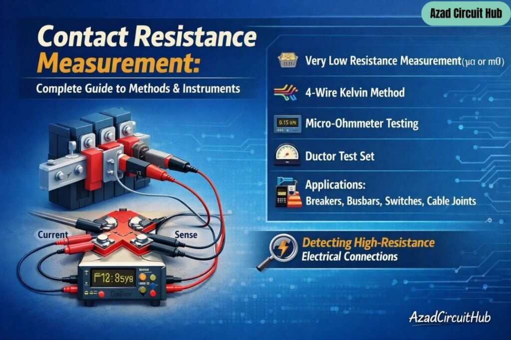
Table of Contents
Table of Contents
Contact Resistance Measurement at a Glance
| Test Item | Typical Requirement |
|---|---|
| Main measurement | Very low resistance |
| Common unit | µΩ or mΩ |
| Preferred method | 4-wire Kelvin method |
| Common instrument | Micro-ohmmeter |
| Traditional instrument | Ductor test set |
| Test current | Depends on equipment and test procedure |
| Main purpose | Detect high-resistance electrical connections |
| Common applications | Breakers, isolators, busbars, switches, cable joints |
The actual acceptable resistance depends on the equipment design, manufacturer data, applicable standard, and previous test results. There is no single micro-ohm value that applies to every switch or circuit breaker.
Why Measure Contact Resistance?
High contact resistance can produce I²R losses. Even a small resistance can generate significant heat when a large current flows continuously through the connection.
For example, if a connection has a resistance of 100 µΩ and carries 1,000 A:
P = I²R
P = 1,000² × 0.0001 = 100 W
That 100 W is concentrated at a small contact area. Over time, heating can cause oxidation, contact damage, insulation deterioration, and further increases in resistance.
Measuring contact resistance helps identify problems such as:
- Loose connections
- Oxidized contact surfaces
- Worn circuit breaker contacts
- Poor busbar joints
- Damaged disconnectors
- Inadequate contact pressure
- Contaminated conductive surfaces
- Mechanical alignment problems
For a detailed reference on applicable testing requirements, see our contact resistance test iec standard guide.
4-Wire Kelvin Method
The 4-wire Kelvin method is one of the most important techniques used for low-resistance testing. It separates the current circuit from the voltage measurement circuit.
Two leads carry the test current through the device under test. Two additional leads measure the voltage directly across the test point.
The resistance is then calculated using:
R = V / I
Because the voltage leads carry very little current, the voltage drop in their lead resistance has minimal influence on the measurement.
| Connection | Function |
|---|---|
| Current lead 1 | Injects test current |
| Current lead 2 | Returns test current |
| Voltage lead 1 | Measures voltage |
| Voltage lead 2 | Measures voltage |
| Instrument | Calculates resistance |
This arrangement is also called a four-terminal or Kelvin connection.
It is particularly useful when measuring very low resistance because ordinary two-wire testing includes the resistance of the test leads and contact points.
Micro-Ohmmeter for Low Resistance Testing
A micro-ohmmeter is designed specifically for low-resistance measurements. Depending on the instrument, it can inject a controlled DC test current and measure the resulting voltage drop with high resolution.
| Instrument Feature | Purpose |
|---|---|
| High test current | Produces measurable voltage drop |
| Kelvin terminals | Reduce lead resistance errors |
| Low resistance range | Measures µΩ and mΩ values |
| Digital display | Provides direct resistance reading |
| Data storage | Records test results |
| Automatic discharge | Helps improve test safety |
When measuring contact resistance, the test current should be appropriate for the equipment and manufacturer’s procedure. Higher current can improve measurement stability, but the test set must be suitable for the device being tested.
Ductor Test Set
A ductor test set is a specialized low-resistance tester traditionally used for checking electrical contacts and joints. The term “ductor” is commonly associated with high-current resistance testing equipment.
Modern ductor instruments generally use the same basic principle as other low-resistance testers: inject current through the connection and measure the voltage drop.
| Ductor Test Set | Micro-Ohmmeter |
|---|---|
| Designed for low resistance | Designed for low resistance |
| Often high-current output | Available with various current ranges |
| Common in switchgear testing | Common in commissioning and maintenance |
| Kelvin connections | Kelvin connections |
| Digital models available | Digital models widely available |
The important point is not the name printed on the instrument. Accuracy, test current, measurement range, lead arrangement, calibration, and test procedure matter more than whether the equipment is called a ductor or micro-ohmmeter.
Measuring Contact Resistance: Test Procedure
A basic test normally follows a controlled sequence.
1. Isolate the Equipment
The equipment must be de-energized, isolated, and properly grounded according to the approved safety procedure. Follow the site switching program and manufacturer’s instructions.
2. Inspect the Connection
Check the terminals, contact surfaces, busbar joints, flexible links, and mechanical connections before testing.
3. Connect the Kelvin Leads
Place the current leads outside the voltage leads. The voltage leads should connect as close as practical to the actual contact or joint being tested.
4. Apply the Test Current
Set the test current according to the equipment procedure. Allow the reading to stabilize when required by the instrument.
5. Record the Resistance
Record the resistance in µΩ or mΩ along with the equipment identification, test current, test location, and test temperature when relevant.
6. Compare the Result
Compare the reading with the manufacturer’s limits, applicable test requirements, previous results, or readings from equivalent phases or poles.
For installations where the applicable requirements need to be checked before testing, our contact resistance test iec standard reference provides a useful starting point.
Factors That Affect the Measurement
Several factors can influence a low-resistance test.
| Factor | Possible Effect |
|---|---|
| Dirty contact surface | Higher resistance |
| Loose connection | Higher resistance |
| Poor lead placement | Measurement error |
| Temperature | Resistance variation |
| Oxidation | Increased resistance |
| Weak contact pressure | Unstable or high readings |
| Lead resistance | Error in two-wire testing |
| Electromagnetic interference | Reading instability |
Temperature is important because conductor resistance changes with temperature. For trending work, measurements should ideally be compared under reasonably similar conditions.
How to Interpret Test Results
A single reading is useful, but trend analysis can be more informative.
For a three-pole circuit breaker, compare the resistance of each pole.
| Pole | Resistance |
|---|---|
| Phase A | 38 µΩ |
| Phase B | 40 µΩ |
| Phase C | 39 µΩ |
These readings are relatively close to each other. A substantially different reading on one pole would justify further investigation, particularly if it differs from previous maintenance records.
The acceptance limit should come from the equipment manufacturer or applicable testing requirements. Do not reject equipment based only on a generic internet value.
Common Testing Mistakes in Contact Resistance Measurement
The most common errors during measuring contact resistance are simple.
- Using a standard multimeter for micro-ohm testing
- Testing without a proper four-wire connection
- Placing voltage leads too far from the actual contact
- Ignoring previous test records
- Comparing different equipment designs as though they were identical
- Failing to clean or inspect suspicious connections
- Applying an unsuitable test current
- Forgetting to document test conditions
A reliable test is more than obtaining a number from a display. The connection method and test conditions are equally important.
For maintenance teams building a complete switchgear test procedure, our contact resistance test iec standard resource can also be used alongside the equipment manufacturer’s instructions.
Frequently Asked Questions
What is contact resistance measurement?
Contact resistance measurement determines the very low electrical resistance of a switch, breaker contact, busbar joint, terminal, or similar conductive connection. Results are normally expressed in micro-ohms or milliohms.
Why is the 4-wire Kelvin method used?
The 4-wire Kelvin method separates the current and voltage circuits. This minimizes the effect of test-lead resistance and allows much more accurate low-resistance measurements.
What is a ductor test set used for?
A ductor test set is used to measure very low electrical resistance in contacts, joints, circuit breakers, disconnectors, busbars, and other high-current connections.
What is a micro-ohmmeter?
A micro-ohmmeter is an instrument designed to measure very low resistance. It normally uses a controlled test current and a Kelvin four-wire connection to obtain accurate results.
What causes high contact resistance?
High readings can result from loose connections, oxidation, contamination, damaged contact surfaces, inadequate contact pressure, mechanical wear, or incorrect testing connections.
Final Takeaway
Contact resistance measurement is an important condition-assessment test for switchgear and high-current electrical connections. The 4-wire Kelvin method provides a reliable way to eliminate much of the error associated with test-lead resistance, while micro-ohmmeters and ductor test sets provide the current and measurement resolution required for these tests.
When measuring contact resistance, always record the test current, resistance value, equipment identification, test location, and relevant conditions. Most importantly, compare the result with manufacturer limits and historical measurements rather than relying on a single generic resistance value.
Get new guides in your feed. Follow Electrical Insights on LinkedIn for new electrical standards guides, calculators and design tips from Azad Circuit Hub.
#ContactResistanceMeasurement, #ElectricalTesting, #ContactResistance, #MicroOhmMeter, #ResistanceTesting, #ElectricalMaintenance, #CircuitBreakerTesting, #ElectricalEngineering, #SwitchgearTesting, #PowerSystemTesting
