
What Is an Insulation Resistance Test? (Definition & How It Works)
An insulation resistance test is an electrical safety test used to check the condition of insulation around wires, cables, motors, transformers, and other electrical equipment. It helps identify insulation that is damaged, damp, contaminated, aged, or breaking down before it causes leakage current, short circuits, electric shock, or equipment failure.
Quick Answer: What Is an Insulation Resistance Test?
| Test Item | Description |
|---|---|
| Purpose | Checks the condition of electrical insulation |
| Main Instrument | Insulation resistance tester, commonly called a megohmmeter or megger |
| Measurement | Resistance in megohms (MΩ) or gigohms (GΩ) |
| Test Supply | DC voltage applied to the insulation |
| Common Test Voltages | 250 V, 500 V, 1000 V DC and higher, depending on equipment |
| Typical Test Points | Conductor-to-earth and conductor-to-conductor |
| High Reading | Generally indicates better insulation condition |
| Low Reading | May indicate moisture, contamination, aging, or insulation damage |
| Main Safety Benefit | Detects insulation deterioration before a fault develops |
In simple terms, an insulation resistance test checks how effectively an insulating material prevents current from flowing where it should not. A good insulation system has very high resistance, while deteriorated insulation allows more leakage current.
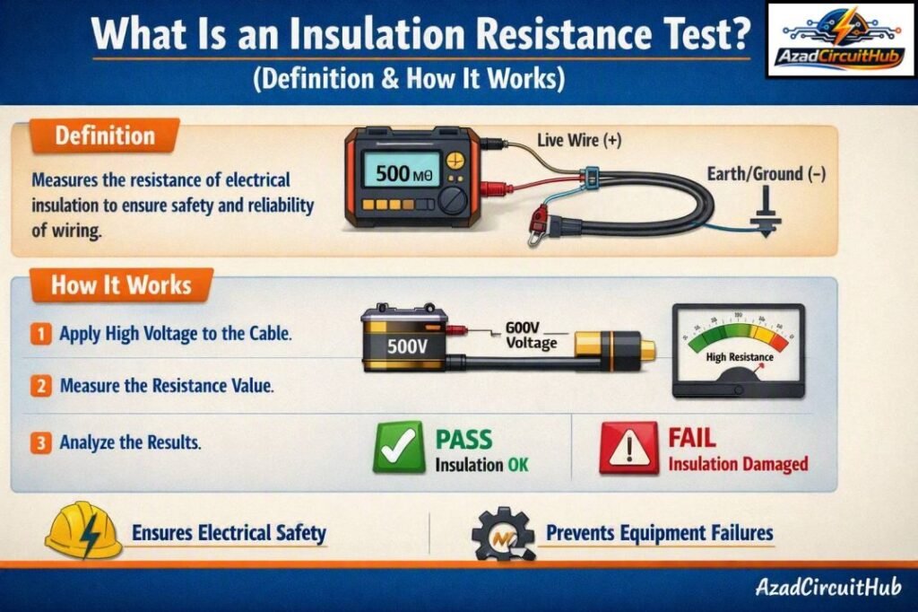
Table of Contents
Table of Contents
What Is Insulation Resistance Testing Used For?
What is insulation resistance testing used for in practical electrical work? It is mainly used to verify that insulation can withstand normal operating conditions without allowing excessive leakage current.
Electricians and electrical engineers commonly perform this test during installation, commissioning, preventive maintenance, troubleshooting, and periodic inspection.
Common applications include:
- Power cables and electrical wiring
- Motors and generators
- Transformers
- Switchgear and distribution boards
- Control panels
- Industrial machinery
- Solar PV cables and equipment
- EV charging circuits
- Heating equipment
- Underground cables
- Industrial control circuits
The test is particularly useful after installation because insulation can be damaged during cable pulling, termination, bending, or equipment assembly.
How Does an Insulation Resistance Test Work?
An insulation resistance tester applies a controlled DC test voltage to the insulation and measures the resulting leakage current. The instrument then calculates resistance using Ohm’s law:
R = V / I
Where:
- R = insulation resistance
- V = applied DC test voltage
- I = leakage current
For example, if a tester applies 500 V DC and measures a leakage current of 0.5 mA:
R = 500 / 0.0005 = 1,000,000 Ω = 1 MΩ
A higher resistance means less leakage current is passing through the insulation.
Basic Insulation Resistance Test Procedure
| Step | Action | Purpose |
|---|---|---|
| 1 | Isolate the circuit | Prevent electric shock and equipment damage |
| 2 | Verify the circuit is de-energized | Confirm there is no live supply |
| 3 | Disconnect sensitive equipment | Protect electronics from DC test voltage |
| 4 | Select the correct test voltage | Match the equipment and applicable standard |
| 5 | Connect the tester | Place leads across the required insulation path |
| 6 | Apply test voltage | Tester measures leakage current |
| 7 | Record resistance | Document the insulation condition |
| 8 | Discharge the circuit | Remove stored electrical charge |
| 9 | Compare with requirements | Determine whether the result is acceptable |
Insulation Resistance Test Explained
An insulation resistance test explained in practical terms is simply a controlled attempt to find unwanted current paths through insulation.
Consider a 230 V or 400 V electrical circuit. The conductors are surrounded by insulation that should prevent current from reaching the equipment enclosure or earth. If the insulation becomes cracked or wet, its resistance can fall.
The tester detects this condition by applying DC voltage and measuring the tiny current flowing through the insulation.
For example:
| Insulation Condition | Resistance Trend | General Meaning |
|---|---|---|
| Excellent | Very high MΩ/GΩ | Very low leakage |
| Good | High MΩ | Insulation is generally healthy |
| Deteriorating | Falling MΩ | Investigate the cause |
| Poor | Low MΩ | Possible insulation fault |
| Severe | Very low resistance | Immediate investigation required |
There is no single resistance value that automatically defines every installation as safe. The acceptable result depends on the applicable electrical standard, circuit voltage, equipment type, and manufacturer’s instructions.
What Voltage Is Used for an Insulation Resistance Test?
The correct test voltage depends on the circuit and equipment being tested. Applying an unnecessarily high voltage can damage sensitive components.
For low-voltage installations, IEC 60364-6 commonly specifies the following verification test voltages and minimum insulation resistance values.
| Circuit Rated Voltage | DC Test Voltage | Minimum Insulation Resistance |
|---|---|---|
| SELV/PELV | 250 V | 0.5 MΩ |
| Up to and including 500 V | 500 V | 1 MΩ |
| Above 500 V | 1000 V | 1 MΩ |
These values are associated with verification of electrical installations under IEC 60364-6. Product-specific standards may require different procedures or acceptance criteria.
The measuring equipment itself is covered by IEC 61557-2, which addresses insulation resistance measurement equipment used in low-voltage distribution systems.
For this reason, technicians should always check the applicable installation standard and manufacturer’s instructions before selecting the test voltage.
Where Is the Insulation Resistance Measured?
What is an insulation resistance test connection supposed to look like? The exact connection depends on the equipment and test objective.
Typical measurements include:
| Test | Connection | What It Checks |
|---|---|---|
| Conductor to earth | Conductor → PE/earth | Insulation to ground |
| Conductor to conductor | L1 → L2 | Phase-to-phase insulation |
| Phase to neutral | L → N | Insulation between conductors |
| Cable core to screen | Core → screen | Core insulation |
| Winding to earth | Winding → frame/earth | Motor or transformer winding insulation |
For a multi-core cable, the test may be performed between individual cores and between the grouped cores and earth or screen, depending on the applicable procedure.
What Instrument Is Used for Insulation Resistance Testing?
An insulation resistance tester is the standard instrument used for this measurement. It is often called a megger, although Megger is also a well-known manufacturer of test equipment.
Modern insulation testers can provide several useful functions.
| Feature | Benefit |
|---|---|
| 250–1000 V DC ranges | Suitable for many low-voltage applications |
| High resistance measurement | Detects weak insulation |
| Automatic discharge | Helps remove stored charge after testing |
| Polarization Index (PI) | Useful for assessing some rotating machines |
| Dielectric Absorption Ratio (DAR) | Helps evaluate insulation behavior over time |
| Digital display | Easy result recording |
| Test timer | Supports timed insulation tests |
Insulation Resistance Test for Motors
Motor insulation testing is widely used in preventive maintenance. The tester can measure resistance between motor windings and the motor frame, with the motor isolated from the supply.
A low reading can indicate moisture, dirt, thermal aging, mechanical damage, or deterioration of winding insulation.
For larger motors, a single resistance reading may not provide enough information. Time-based tests such as PI or DAR can provide additional insight into insulation condition when recommended by the equipment manufacturer or applicable standard.
Insulation Resistance Test for Cables
Cable insulation testing is commonly performed after installation and during maintenance.
For a multi-core cable, technicians may check:
- Core-to-core insulation
- Core-to-earth insulation
- Core-to-screen insulation
- Insulation between conductors and metallic sheath
The result should be recorded with the test voltage, test duration, cable identification, temperature, and test conditions where relevant.
Temperature can significantly affect insulation resistance, particularly in larger cables and rotating machines. Comparing results taken under similar conditions gives a more useful indication of insulation deterioration.
Factors That Affect Insulation Resistance
What is an insulation resistance test result affected by? Several environmental and physical conditions can change the measured value.
| Factor | Effect on Resistance |
|---|---|
| Moisture | Usually lowers insulation resistance |
| Temperature | Resistance generally decreases as temperature rises |
| Dirt and contamination | Can create leakage paths |
| Cable age | Insulation may deteriorate over time |
| Mechanical damage | Can reduce resistance significantly |
| Chemical exposure | May attack insulation materials |
| Surface leakage | Can produce misleadingly low readings |
| Test duration | Resistance may change during the test |
This is why maintenance teams should not look at one number in isolation. Trending test results over time is often more useful than comparing readings without considering test conditions.
Safety Precautions Before Testing
Before performing an insulation resistance test, follow the correct electrical isolation procedure. The test voltage can be hazardous, and the circuit may retain charge after the test.
Important precautions include:
- Switch off and isolate the electrical supply.
- Apply the required lockout/tagout procedure.
- Verify absence of voltage with an appropriate tester.
- Disconnect sensitive electronic equipment when required.
- Select the correct insulation test voltage.
- Keep unauthorized personnel away from the test area.
- Do not touch the circuit during testing.
- Allow the circuit to discharge after testing.
- Verify that stored voltage has fallen to a safe level before handling conductors.
Equipment such as variable frequency drives, electronic controls, surge protective devices, and other sensitive components may require disconnection before applying an insulation resistance test.
Insulation Resistance vs Continuity Test
An insulation resistance test and a continuity test serve different purposes.
| Feature | Insulation Resistance Test | Continuity Test |
|---|---|---|
| Main purpose | Checks insulation quality | Checks whether a conductive path exists |
| Test voltage | Usually higher DC voltage | Usually low test voltage |
| Measurement | MΩ or GΩ | Ω |
| Main concern | Unwanted current through insulation | Broken or high-resistance conductor |
| Typical application | Cable insulation, motors, circuits | Protective conductors, wiring, connections |
A continuity test can confirm that a conductor is connected, but it cannot replace insulation resistance testing.
Why Is Insulation Resistance Testing Important?
Regular insulation testing helps identify developing electrical problems before they become serious faults. It can reduce unexpected downtime, improve electrical safety, and support preventive maintenance programs.
A falling insulation resistance trend may be an early warning of moisture ingress, thermal stress, contamination, or insulation aging.
For industrial plants, documenting test results also helps maintenance teams compare equipment performance over months or years.
For a broader guide to electrical insulation requirements and test methods, see our iec standard for insulation resistance test guide, which covers applicable IEC requirements and practical test considerations.
How Does a Megger Insulation Tester Work?
A Megger insulation tester applies a controlled DC test voltage to electrical insulation and measures the resulting leakage current. The instrument then calculates insulation resistance, usually displayed in megohms (MΩ). This is the basic megger working principle behind an Insulation Resistance Test.
Unlike a normal multimeter, a Megger can generate much higher DC test voltages, commonly 250 V, 500 V, 1000 V, 2.5 kV, and 5 kV, depending on the model and application.
Megger Working Principle and Test Voltage
| Application | Typical DC Test Voltage | Common Use |
|---|---|---|
| Low-voltage control circuits | 250 V | PLC, control and instrumentation circuits |
| 230/400 V equipment | 500 V | Motors, cables and distribution circuits |
| Higher-voltage LV equipment | 1000 V | Motors, transformers and power cables |
| Medium-voltage equipment | 2.5 kV | MV motors, cables and switchgear |
| High-voltage equipment | 5 kV or higher | Transformers, generators and HV cables |
The tester applies DC voltage between the conductor and earth, or between two conductors. Good insulation allows only a very small leakage current. Since resistance is calculated from voltage and current, the tester can determine insulation resistance using the relationship:
R = V / I
How Does a Megger Produce 1000V?
A modern digital Megger generally uses an internal battery and electronic voltage-conversion circuitry to increase the battery voltage to the selected test voltage. Older hand-cranked generator-type Meggers use a mechanical generator to produce the required high DC voltage.
The important point is that the tester produces a high voltage at very low current. The 1000 V setting does not mean the instrument supplies 1000 V continuously into a load like a power source; it is a controlled test voltage intended for insulation testing.
Types of Megger
| Type | Power Source | Typical Application |
|---|---|---|
| Hand-cranked Megger | Internal generator | Field testing without batteries |
| Digital Megger | Battery | General electrical maintenance |
| Analog Megger | Battery/generator | Traditional insulation testing |
| High-voltage insulation tester | Battery/mains | Motors, transformers and HV equipment |
| Automatic diagnostic tester | Battery/mains | PI, DAR and advanced insulation analysis |
Generator Megger Test Procedure
For generator insulation testing with a Megger, first isolate the generator from all external sources and discharge the winding. Disconnect sensitive electronic equipment where required by the manufacturer’s procedure. Connect the tester between the winding under test and the generator frame/earth, select the appropriate test voltage, and apply the test for the specified duration.
Record the insulation resistance and compare it with previous test results and the manufacturer’s limits. After testing, discharge the winding safely because the winding can retain a potentially dangerous charge.
Common Causes of Low Insulation Resistance
A low reading does not always mean that the cable or equipment must be replaced. The cause should be investigated.
Common causes include:
- Water or moisture penetration
- Damaged cable insulation
- Poor cable termination
- Dust and conductive contamination
- Oil or chemical contamination
- Overheating
- Aging insulation
- Incorrect wiring
- Connected electronic equipment
- Surface tracking
Cleaning, drying, repairing, or isolating the affected section may improve the measurement. However, repairs should follow the applicable electrical safety procedures and equipment requirements.
How to Interpret Insulation Resistance Test Results
The most important point is that a higher resistance reading is generally desirable, but acceptance must be based on the relevant standard or manufacturer’s specification.
A useful maintenance record should include:
| Recorded Information | Example |
|---|---|
| Equipment | Motor M-101 |
| Circuit voltage | 400 V |
| Test voltage | 500 V DC |
| Test duration | 60 seconds |
| Insulation resistance | 250 MΩ |
| Ambient temperature | 25°C |
| Humidity | Recorded where relevant |
| Test points | Winding-to-earth |
| Result | Compared with applicable requirement |
For critical equipment, recording results over time allows engineers to identify gradual deterioration rather than waiting for a sudden failure.
If you are also working on electrical installation verification, our guide to the iec standard for insulation resistance test provides a useful reference for selecting test methods, voltages, and acceptance requirements.
Frequently Asked Questions
What is an insulation resistance test?
What is an insulation resistance test? It is a test that applies a controlled DC voltage to electrical insulation and measures its resistance. The result is normally displayed in megohms or gigohms, with higher resistance generally indicating better insulation performance.
What is a good insulation resistance reading?
There is no universal value for every electrical system. For many low-voltage installations, IEC 60364-6 specifies minimum values such as 1 MΩ for circuits up to and including 500 V, but equipment-specific requirements can be different. Always use the applicable standard and manufacturer’s instructions.
What is insulation resistance testing used to detect?
It can identify insulation deterioration caused by moisture, contamination, aging, overheating, cracking, mechanical damage, and other unwanted leakage paths. It is commonly used for cables, motors, transformers, switchgear, and electrical installations.
What voltage is used for an insulation resistance test?
Common DC test voltages include 250 V, 500 V, and 1000 V, depending on the circuit and equipment. IEC 60364-6 provides test voltage requirements for electrical installation verification, while product standards may specify different values.
How often should insulation resistance testing be done?
The frequency depends on the type of installation, equipment, operating environment, maintenance program, and applicable regulations. New installations are commonly tested during verification, while industrial equipment may be tested periodically as part of preventive maintenance.
Final Takeaway
What is an insulation resistance test? It is a practical method for checking whether electrical insulation is still providing adequate separation between conductors and earth or between different conductive parts.
The test uses a DC voltage and measures resistance in MΩ or GΩ. A high reading normally indicates low leakage, while a declining reading can point to insulation deterioration.
For reliable results, use the correct test voltage, isolate sensitive equipment, follow electrical safety procedures, and compare readings with the applicable standard or manufacturer’s requirements. Most importantly, maintain a history of test results so gradual insulation deterioration can be identified before it develops into an electrical fault.
For more detailed electrical testing guidance, refer to our iec standard for insulation resistance test resource for related IEC requirements, test voltages, and practical verification guidance.
Follow Us on Social:
Subscribe our Newsletter on Electrical Insights for latest updates from Azad Circuit Hub
#InsulationResistanceTest, #InsulationResistanceTesting, #ElectricalTesting, #MeggerTest, #ElectricalSafety, #ElectricalMaintenance, #InsulationTesting, #Megohmmeter, #ElectricalEngineering, #PreventiveMaintenance
