Submersible Motor Winding Resistance Chart: Ohm Values and Testing Guide
A submersible motor winding resistance chart helps electricians and pump technicians check winding condition, identify open circuits, and detect possible winding faults. By measuring resistance between motor leads, you can compare readings, find phase imbalances, and decide whether further testing is needed.
The correct resistance depends on motor power, voltage, phase, winding design, and temperature. A resistance reading alone cannot confirm that a motor is healthy. Insulation resistance, cable condition, supply voltage, and manufacturer specifications must also be checked.
Submersible Motor Winding Resistance Chart
The following Submersible Motor Winding Resistance Chart provides illustrative phase-to-phase resistance ranges for copper-wound, three-phase submersible motors. These are broad screening estimates, not universal manufacturer specifications. Actual values can differ significantly between 230 V, 400 V, and 460 V motors.
| Motor Power | Typical Resistance Trend | Expected Phase Balance |
|---|---|---|
| 0.5 HP | Relatively high resistance | Similar readings |
| 1 HP | High to moderate resistance | Similar readings |
| 2 HP | Moderate resistance | Similar readings |
| 3 HP | Moderate resistance | Similar readings |
| 5 HP | Lower resistance | Similar readings |
| 7.5 HP | Low resistance | Similar readings |
| 10 HP | Low resistance | Similar readings |
| 15 HP | Very low resistance | Similar readings |
| 20 HP | Very low resistance | Similar readings |
| 25 HP and above | Often very low resistance | Similar readings |
Exact ohm values should be obtained from the motor manufacturer or its service manual. Motor horsepower alone is not enough to establish a reliable resistance range.
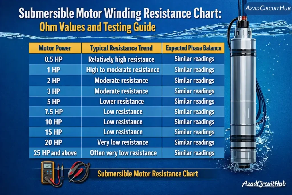
Table of Contents
Table of Contents
Three-Phase Submersible Motor Resistance Measurements
For a three-phase motor with three accessible leads marked U, V, and W, measure resistance between each pair.
| Test | Meter Connection | Healthy Result |
|---|---|---|
| Winding 1 | U–V | Stable resistance |
| Winding 2 | V–W | Similar resistance |
| Winding 3 | W–U | Similar resistance |
| Open winding check | Each lead pair | No open circuit |
| Insulation test | Winding to earth | High insulation resistance |
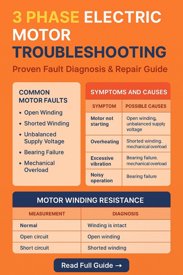
For more detailed reference values, see the motor winding resistance chart for additional motor sizes and voltage ratings.
Expert Field Note
When checking submersible pumps in the field, I compare all accessible winding resistance readings before judging a motor. I also check cable joints, moisture ingress, and insulation resistance, because a balanced winding reading does not rule out an earth fault or damaged insulation.
How to Calculate Motor Winding Resistance Imbalance
Resistance imbalance shows how far the measured winding values differ from their average. This calculation is useful when comparing three-phase motor windings.
Formula:
Resistance Imbalance (%) = (Maximum Deviation from Average Resistance / Average Resistance) × 100
First, calculate the average:
Average Resistance = (R1 + R2 + R3) / 3
Example:
Suppose the measured values are:
- U–V = 2.0 Ω
- V–W = 2.1 Ω
- W–U = 1.9 Ω
Average resistance:
Average = (2.0 + 2.1 + 1.9) / 3 = 2.0 Ω
Maximum deviation = 0.1 Ω
Resistance imbalance = (0.1 / 2.0) × 100 = 5%
This indicates a 5% resistance imbalance. Investigate the cause and compare the result with the manufacturer’s acceptance limits. Do not treat this example as a universal pass/fail threshold.
You can also consult 3 phase motor winding resistance values to compare measurements with broader motor testing references.
How to Check Submersible Motor Winding Resistance
Follow these steps to check the motor windings safely.
- Switch off and isolate the power supply.
- Apply lockout/tagout procedures and verify that the circuit is de-energized.
- Disconnect the motor cable from the control panel or starter.
- Identify the motor leads according to the wiring diagram.
- Set a suitable multimeter to the lowest resistance range.
- Measure resistance between each accessible pair of motor leads.
- Record the results and compare the readings.
- Check each winding lead against earth using a suitable insulation resistance tester.
For low-resistance windings, lead resistance can affect readings. Short the meter probes together first and account for their resistance. A four-wire low-resistance meter provides better accuracy when very low ohm values must be measured.
For additional three-phase testing guidance, use the 3 phase motor winding resistance chart.
What Do Abnormal Resistance Readings Mean?
| Reading or Observation | Possible Cause | Recommended Action |
|---|---|---|
| OL or infinite resistance | Open winding, broken cable, or poor connection | Check the cable and connections |
| Near-zero resistance | Short circuit or measurement setup issue | Verify the meter and test the winding |
| One phase differs significantly | Winding damage, joint fault, or connection issue | Repeat measurements and inspect connections |
| Similar resistance on all phases | Windings may be electrically balanced | Perform insulation and other required tests |
| Resistance changes when cable moves | Loose joint or damaged conductor | Inspect the cable and splice |
| Low insulation resistance | Moisture, damaged insulation, or contamination | Investigate before energizing |
A normal winding resistance reading does not prove that the insulation is healthy. A motor can have balanced winding resistance and still suffer from insulation breakdown.
What Happens When Submersible Motor Windings Burn Up?
Burned windings can result from prolonged overload, dry running, blocked cooling, low or unbalanced supply voltage, frequent starts, water ingress, or insulation failure.
Typical signs include:
- Repeated overload trips
- A burnt smell from the motor or control equipment
- Abnormally high current
- Poor starting or failure to start
- Low insulation resistance
- Discolored or damaged winding insulation during inspection
A burnt winding often requires professional repair or motor replacement. Do not repeatedly reset the overload relay without finding the cause.
Frequently Asked Questions
1. How many ohms should a motor winding have?
There is no single correct ohm value for every motor. Small motors may have several ohms of winding resistance, while larger motors may measure well below one ohm. Check the manufacturer’s data and compare phase-to-phase readings.
2. How to check submersible motor winding?
Isolate the power, disconnect the motor leads, and measure resistance between each accessible pair with a multimeter. Compare the results, check for open circuits, and perform an insulation resistance test using suitable equipment.
3. What happens when submersible motor windings burn up?
The motor may stop running, draw abnormal current, trip its protection, or fail to start. Burned windings usually indicate overheating or insulation damage. The underlying cause must be corrected before the motor is repaired or replaced.
4. How to test a submersible motor?
Check supply voltage, cable continuity, winding resistance, insulation resistance, and operating current. Also inspect the starter, overload protection, cable joints, and pump conditions. Follow the manufacturer’s testing procedure and electrical safety requirements.
5. How to tell if motor windings are bad with a multimeter?
An open-circuit reading, a major difference between comparable winding readings, or an unexpected near-zero reading can indicate a fault. However, a standard multimeter cannot reliably detect every turn-to-turn short. Additional motor testing may be required.
6. What is a bad Megger reading for a motor?
A low insulation resistance reading can indicate moisture, contamination, or damaged insulation. The acceptable minimum depends on motor rating, voltage, temperature, manufacturer guidance, and the applicable testing standard. Do not use one universal threshold for every submersible motor. Disconnect sensitive electronics before testing and follow the manufacturer’s specified test voltage.
Final Recommendations
A submersible motor winding resistance chart is a useful starting point for troubleshooting, but measured values must be interpreted in context. Compare all winding pairs, account for test-lead resistance, inspect cable connections, and check insulation resistance before concluding that the motor is defective.
Always follow the manufacturer’s service instructions and applicable electrical safety rules. If winding readings are abnormal or insulation resistance is poor, keep the motor isolated until the fault has been investigated.
Get new guides in your feed. Follow Electrical Insights on LinkedIn for new electrical standards guides, calculators and design tips from Azad Circuit Hub.