How to Calculate Busbar Size for Panel
Knowing how to calculate busbar size for panel assemblies is a core skill for every electrical engineer and technician. A poorly sized busbar can lead to overheating, voltage drop, nuisance tripping, and even catastrophic panel failure. On the other hand, oversizing without a method increases copper cost and reduces project competitiveness.
In practical panel design, the goal is to select a conductor that safely carries the full load current, withstands short-circuit stress, and maintains acceptable temperature rise. This article explains a field-tested approach used in switchboard and distribution panel manufacturing. The method is simple, accurate, and aligned with real operating conditions.
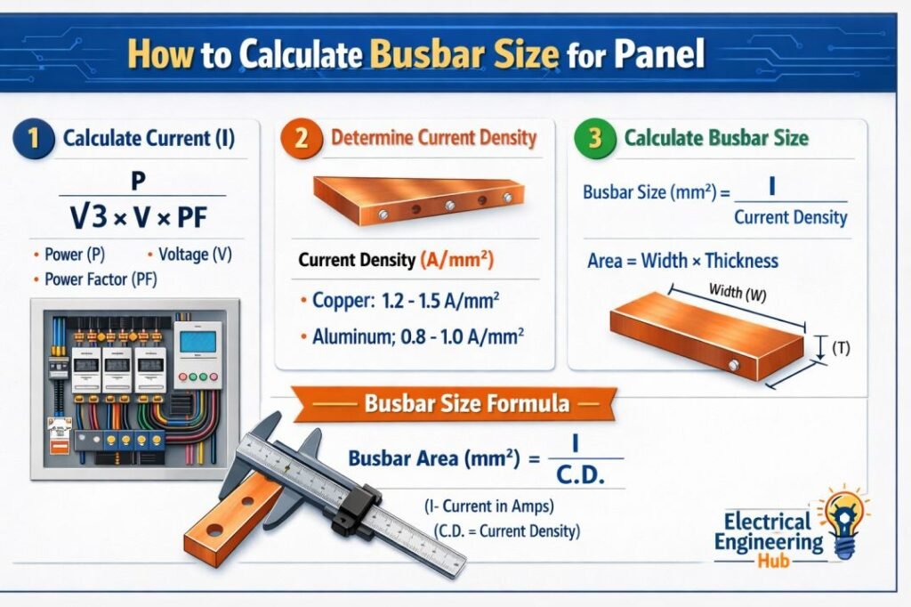
Table of Contents
Table of Contents
Why Correct Busbar Sizing Matters
When engineers calculate busbar size for panel layouts, they are balancing electrical safety, thermal performance, and cost. Busbars carry high current continuously, often inside enclosed panels where heat dissipation is limited.
If the current density is too high, insulation materials age faster and protective devices may trip unexpectedly. High temperature also increases resistance, which causes additional power loss. Proper sizing ensures reliable power distribution and long service life.
Correct selection also improves mechanical strength during fault conditions. Busbars must withstand electrodynamic forces during short circuits without deformation.
Basic Parameters to Calculate Busbar Size for Panel
Before you calculate busbar size for panel applications, gather accurate design inputs. These parameters define the operating and fault conditions.
Table 1: Essential Data for Busbar Calculation
| Parameter | Description | Typical Source |
|---|---|---|
| Rated Current (A) | Maximum continuous load current | Load schedule or feeder rating |
| System Voltage | Determines insulation clearance | Single line diagram |
| Material Type | Copper or aluminum busbar | Design specification |
| Ambient Temperature | Panel installation environment | Site condition |
| Enclosure Type | Ventilated or enclosed panel | Panel design |
| Short Circuit Level (kA) | Fault withstand requirement | Protection study |
Having reliable values prevents guesswork and ensures accurate conductor selection.
Step-by-Step Method to Calculate Busbar Size for Panel
A practical engineering approach starts with the continuous current rating and then verifies thermal and fault withstand capacity.
Step 1: Determine Full Load Current
Calculate the expected current using standard electrical formulas.
For three-phase systems:
Current (A) = Power (kW) / (√3 × Voltage × Power Factor × Efficiency)
Always consider future expansion by adding a margin of 20 to 25 percent.
Step 2: Select Allowable Current Density
Current density depends on busbar material and cooling conditions.
Table 2: Typical Current Density Values
| Material | Enclosed Panel | Open Air |
|---|---|---|
| Copper | 1.2 to 1.6 A/mm² | 1.6 to 2.0 A/mm² |
| Aluminum | 0.8 to 1.0 A/mm² | 1.0 to 1.2 A/mm² |
For most indoor distribution boards, engineers use about 1.5 A/mm² for copper.
Step 3: Calculate Required Cross-Sectional Area
Area (mm²) = Load Current / Current Density
If the calculated area is 800 mm², you can select standard dimensions such as 100 mm × 8 mm copper bar.
This stage is the core step when you calculate busbar size for panel projects because it determines the conductor thickness and width. Use our online tool for accurate busbar size calculation according to IEC and NEC standards.
Step 4: Select Standard Busbar Dimensions
Manufacturers provide standard sizes that simplify fabrication and installation.
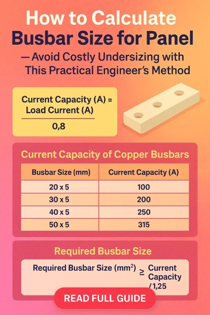
Table 3: Common Copper Busbar Sizes
| Width (mm) | Thickness (mm) | Area (mm²) | Approx Current Capacity (A) |
|---|---|---|---|
| 25 | 5 | 125 | 180 |
| 50 | 6 | 300 | 450 |
| 75 | 8 | 600 | 900 |
| 100 | 10 | 1000 | 1500 |
Choose a size equal to or greater than the required cross-section.
Step 5: Verify Temperature Rise
Busbar temperature must remain within insulation class limits. Use derating factors if ambient temperature exceeds standard conditions.
Ventilation slots or forced cooling can improve heat dissipation. In compact panels, consider multiple busbars in parallel instead of a single thick bar.
Step 6: Check Short Circuit Withstand Capacity
Busbars must survive thermal stress during fault current flow.
Short circuit withstand formula:
S = (I × √t) / k
Where S is cross-sectional area, I is fault current, t is duration, and k is material constant.
Copper typically has higher fault withstand capability compared to aluminum. This check is essential after you calculate busbar size for panel current capacity.
Practical Example from a Distribution Panel
Consider a three-phase panel rated at 1200 A using copper busbars.
- Using current density of 1.5 A/mm²:
- Required Area = 1200 / 1.5 = 800 mm²
- Select standard busbar size 100 mm × 8 mm, which provides 800 mm².
Next, confirm short circuit level is within withstand limits. If the system fault level is high, use two parallel bars of 80 mm × 8 mm to improve strength and heat distribution.
This practical approach ensures the selected conductor operates safely under continuous and fault conditions.
Copper vs Aluminum Busbar Selection
Many engineers compare materials before they calculate busbar size for panel assemblies.
Copper offers lower resistance, better conductivity, and higher mechanical strength. It also requires less cross-section for the same current rating.
Aluminum is lighter and more economical but needs larger size to carry equal current. Jointing methods and oxidation protection must be carefully handled.
Table 4: Comparison of Busbar Materials
| Feature | Copper | Aluminum |
|---|---|---|
| Conductivity | High | Moderate |
| Cost | Higher | Lower |
| Mechanical Strength | Excellent | Moderate |
| Space Requirement | Compact | Larger |
For compact switchboards and high current feeders, copper remains the preferred option.
Installation Practices That Improve Performance
Even when you calculate busbar size for panel designs correctly, poor installation can reduce performance.
Maintain proper phase spacing to avoid overheating. Use insulated supports with adequate creepage distance. Tighten joints with calibrated torque to minimize contact resistance.
Surface treatment such as tin plating improves corrosion resistance and connection reliability. Ensure sharp edges are removed to prevent insulation damage.
Common Mistakes That Lead to Undersizing
Engineers sometimes rely only on rule-of-thumb values without verifying real load conditions. Ignoring ambient temperature or enclosure ventilation can cause overheating.
Another frequent mistake is neglecting fault level checks. A busbar that carries load current safely may still deform during a short circuit event.
Selecting non-standard dimensions also complicates fabrication and increases lead time. Always match calculated area with available manufacturer sizes. To avoid mistakes use our online tool busbar size calculator
Best Practices for Reliable Panel Design
Use conservative current density values for enclosed panels. Add expansion margin to accommodate future load growth.
Verify both thermal and electrodynamic withstand capacity. Maintain proper support spacing to prevent vibration during faults.
Document all assumptions in the design calculation sheet. This improves traceability during inspection and commissioning.
By following this structured approach, engineers can consistently calculate busbar size for panel installations with confidence and accuracy.
Related Guide & Tools
Conclusion
Accurate busbar selection is essential for safe and efficient power distribution. When you calculate busbar size for panel assemblies using a practical method, you reduce overheating risk, improve reliability, and control project cost.
Start with the true load current, apply realistic current density, select standard dimensions, and confirm short circuit withstand capability. Combine these steps with good installation practice to achieve long service life.
A disciplined calculation process protects equipment, ensures compliance with electrical standards, and prevents costly redesign later in the project lifecycle.
Get new guides in your feed. Follow Electrical Insights on LinkedIn for new electrical standards guides, calculators and design tips from Azad Circuit Hub.
#BusbarSizeCalculation, #ElectricalPanelDesign, #BusbarSizing, #ElectricalEngineeringTips, #SwitchgearDesign, #PowerDistribution, #ElectricalCalculations, #PanelBuilding, #EngineeringGuide, #ElectricalStandards