DC Current Transformer Working Principle: Important Concepts
The DC current transformer working principle is essential to understand how these devices operate and are indispensable in various industrial applications. Unlike their AC counterparts, DC current transformers are specifically designed to measure direct current (DC) rather than alternating current (AC).
A DC (Direct Current) transformer is a transformer used in electrical systems for a variety of tasks, including monitoring, protection, and control. It measures high DC currents and transforms them into lower, quantifiable levels. DC current transformers work on the principles of magnetic saturation and Faraday’s law of electromagnetic induction, as opposed to AC current transformers, which are more typical.

Read More About
In this detailed explanation, we will discuss the DC current transformer working principle, elucidating its components and operation.
DC Current Transformer Working Principle
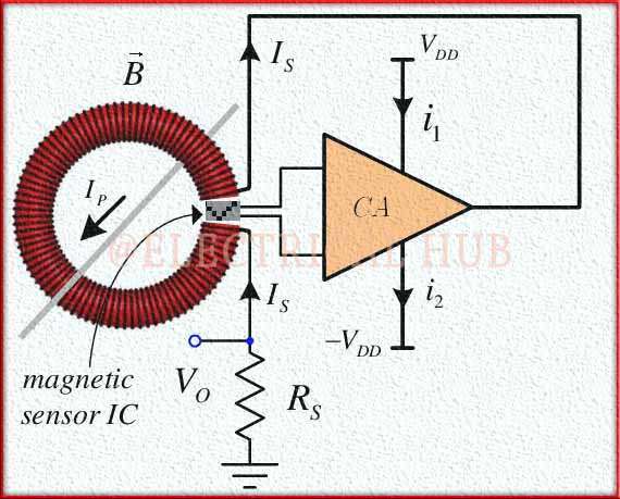
At the heart of the DC current transformer working principle is its core and coil arrangement. Similar to AC transformers, DC current transformers consist of a magnetic core and primary and secondary windings. The primary winding, typically consisting of a single turn or a few turns of a thick conductor, is connected in series with the DC circuit carrying the current to be measured.
A magnetic core used in DC transformers is comprised of materials that are magnetically susceptible to saturation. When the core material can no longer absorb any more magnetic flux, magnetic saturation occurs. The operation of DC transformers depends on this saturation feature.
Magnetic Field Creation
When DC current flows through the primary winding, it generates a magnetic field within the core. The magnetic field’s strength is directly proportional to the magnitude of the DC current, by the DC current transformer working principle.
A hole or aperture is made in the magnetic core of the transformer for the DC conductor carrying the high current that will be measured. The core surrounds the conductor but does not create a closed magnetic loop, unlike AC transformers.
Secondary Winding
Adjacent to the primary winding, the secondary winding comprises many more turns of fine wire, allowing for voltage isolation and current transformation. The DC current transformer working principle relies on Faraday’s law of electromagnetic induction. As the magnetic field from the primary winding cuts across the secondary winding, it induces a proportional voltage across the secondary winding.
Due to the right-hand rule, when a DC passes through the conductor inside the core, it creates a magnetic field all around the conductor. In the core, this magnetic field causes a magnetic flux.
Polarity and Direction
It’s crucial to note that the DC current transformer working principle takes into account the polarity and direction of the DC. The direction of the induced voltage in the secondary winding depends on the direction of the DC in the primary circuit, adhering to the right-hand rule.
As the DC increases, the magnetic core begins to saturate, meaning it cannot absorb any more magnetic flux. This is because the core material is designed to reach saturation at a specific point. When saturation occurs, the rate of change of magnetic flux in the core levels off.
Output Voltage
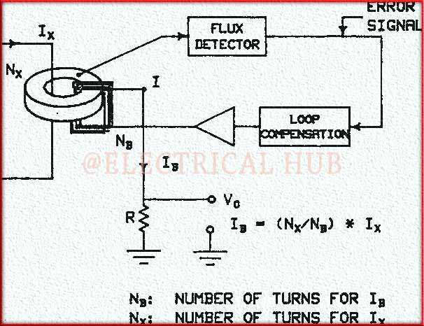
The induced voltage in the secondary winding is a scaled-down representation of the primary current. The turn ratio between the primary and secondary windings determines the transformation ratio, allowing the DC transformer to output a manageable and measurable voltage signal.
A change in magnetic flux causes a voltage to be induced in a neighboring coil or winding, by Faraday’s law of electromagnetic induction. A secondary winding is coiled around the magnetic core in a DC transformer. The secondary winding’s voltage is produced by the change in magnetic flux brought on by the DC.
The primary DC current flowing through the conductor determines the voltage induced in the secondary winding. The measured induced voltage can subsequently be employed for a variety of tasks in electrical systems, including monitoring, regulation, and protection.

Load Resistance
The secondary winding of the DC transformer is connected to a load resistance. The DC current transformer working principle dictates that the voltage across this load resistance is directly proportional to the primary current, ensuring accurate current measurement.
Isolation
One of the advantages of DC transformers is their ability to provide electrical isolation between the primary and secondary circuits. This feature is crucial for safety and allows for measurements in high-voltage environments.
Output Signal
The output signal from the DC transformer can be further processed by electronics, such as analog-to-digital converters or amplifiers, to make it suitable for monitoring or control systems. This is an essential aspect of the DC current transformer working principle in modern applications.
In summary, the DC current transformer working principle hinges on the generation of a magnetic field by the primary winding, inducing a proportional voltage in the secondary winding. This induced voltage serves as a scaled-down representation of the primary DC, allowing for accurate and safe measurement.
Understanding the DC current transformer working principle is fundamental for engineers and technicians working with direct current systems in various industries. It’s vital to remember that DC current converters often have limitations on the highest DC current they can accurately detect and are created for specified current ranges.
Furthermore, because magnetic saturation is involved, they are not appropriate for monitoring very low DC currents, and accuracy may decline as the current approaches the saturation limit of the transformer. Therefore, it’s crucial to choose the right DC current transformer for the required application.
Follow us on LinkedIn”Electrical Insights” to get the latest updates in Electrical Engineering. You can also Follow us on LinkedIn and Facebook to see our latest posts on Electrical Engineering Topics.
Worth Read Posts
