A4988 Stepper Motor Driver with ESP32 Microcontroller: Important Guide
Using the A4988 Stepper Motor Driver with the ESP32 microcontroller is a straightforward process, allowing you to control stepper motors for various applications. Below is a basic guide on connecting the A4988 to an ESP32 and an example code snippet to get you started.
Table of Contents

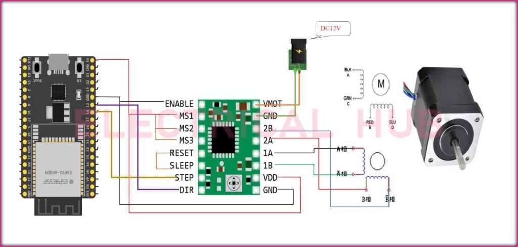
Connecting A4988 Stepper Motor Driver to ESP32:
Power Supply Connection:
- Connect the VMOT pin of the A4988 to the motor power supply voltage (typically between 8V and 35V).
- Connect GND to the ground of the power supply.
Logic Supply Connection:
- Connect VDD to the logic power supply voltage (usually between 3V and 5.5V).
- Connect GND to the ground of the ESP32.
Motor Connections:
- Connect one coil of the stepper motor to the A1 and A2 pins and the other coil to the B1 and B2 pins on the A4988.
Control Pins:
- Connect the DIR (Direction) pin to a digital output pin on the ESP32.
- Connect the STEP pin to another digital output pin on the ESP32.
If you want to control microstepping, connect the MS1, MS2, and MS3 pins to the appropriate digital output pins on the ESP32.

Adjustable Current Limit:
Connect the VREF pin to a potentiometer. Adjusting the potentiometer allows you to set the motor current to prevent overheating.
Enable and Sleep Control (Optional):
Connect the ENABLE and SLEEP pins to digital output pins on the ESP32 if you want to control motor enable/disable and sleep modes.
ESP32 Code for A4988 Stepper Motor Driver:
Below is a simple example code using the ESP32 Arduino library to control a stepper motor with the A4988 driver. Make sure to install the AccelStepper library in the Arduino IDE before uploading the code.
#include <AccelStepper.h>

// Define motor connections

#define DIR_PIN 2

#define STEP_PIN 3

// Create a stepper motor object

AccelStepper stepper(1, STEP_PIN, DIR_PIN);

void setup() {

  // Set motor speed and acceleration

  stepper.setMaxSpeed(1000);

  stepper.setAcceleration(500);

}

void loop() {

  // Rotate the motor one revolution

  stepper.moveTo(200);

  stepper.runToPosition();

  delay(1000);

  // Rotate the motor in the opposite direction

  stepper.moveTo(0);

  stepper.runToPosition();

  delay(1000);

}
This code is similar to the previous example for Arduino, utilizing the AccelStepper library to control the stepper motor with the A4988 driver. Adjust the DIR and STEP pin definitions according to your ESP32 GPIO pin configuration.
By combining the A4988 Stepper Motor Driver with an ESP32 and the appropriate code, you can achieve precise and controlled motion for your projects, providing a versatile solution for applications such as robotics, CNC machines, or any project requiring accurate stepper motor control.
Worth Read Posts
Follow us on LinkedIn”Electrical Insights” to get the latest updates in Electrical Engineering. You can also Follow us on LinkedIn and Facebook to see our latest posts on Electrical Engineering Topics.


I think this website has some real excellent information for everyone : D.