OR GATE: Truth Table and Important Types
Read More About
Introduction
An OR gate is a building block of digital logic circuits. It takes multiple binary inputs and produces a single output based on the logic of the OR operation. The OR operation is akin to logical addition, where the output is “1” if any of the inputs are “1”, and “0” only if all the inputs are “0”.

The OR can have two or more inputs, although the most common types have two or three inputs. Each input can either be high (1) or low (0). The output of the OR reflects the logical result of the OR operation performed on the input values.
Let’s consider an example with two inputs, A and B. The truth table for the OR would look like this:
| Input A | Input B | Output |
| 0 | 0 | 0 |
| 0 | 1 | 1 |
| 1 | 0 | 1 |
| 1 | 1 | 1 |
In this truth table, we can see that if both inputs A and B are “0” (low), the output of the OR is “0” (low). However, if either input A or B (or both) is “1” (high), the output of the OR becomes “1” (high).
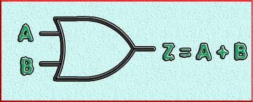
The logic symbol for an OR is often depicted as a curved “V” with inputs on the left side and the output on the right side. The inputs are represented by lines extending into the gate, and the output is indicated by a single line coming out of the gate. Sometimes, the OR symbol is also represented by a “+” sign.
The functionality of the OR is utilized in various applications, such as data processing, arithmetic circuits, control systems, and more. It is a fundamental component in the design and implementation of digital systems, enabling logical operations to be performed on binary data.
3-input logic OR gate
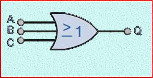
A 3-input logic OR gate is a digital circuit that performs the logical OR operation on three binary inputs. It produces a single output that represents the result of the OR operation. The logic symbol for a 3-input OR typically consists of three inputs (A, B, and C) and a single output. It can be represented as follows:

The truth table for a 3-input OR lists all possible combinations of input values and their corresponding output:
| Input A | Input B | Input C | Output |
| 0 | 0 | 0 | 0 |
| 0 | 0 | 1 | 1 |
| 0 | 1 | 0 | 1 |
| 0 | 1 | 1 | 1 |
| 1 | 0 | 0 | 1 |
| 1 | 0 | 1 | 1 |
| 1 | 1 | 0 | 1 |
| 1 | 1 | 1 | 1 |
In this truth table, the inputs A, B, and C represent the binary values (0 or 1), and the output represents the result of the logical OR operation performed on the inputs.
The output of the 3-input OR is “1” if any of the inputs A, B, or C is “1”. Only if all three inputs are “0” will the output be “0”. This behavior is consistent with the logical OR operation, where the output is “1” if any of the inputs are “1”, and “0” if all the inputs are “0”.
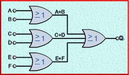
6-Input OR-Gate

9-input OR gate
A 9-input OR gate is a digital circuit that performs the logical OR operation on nine binary inputs. It produces a single output that represents the result of the OR operation. While the logic symbol for a 9-input OR gate can become complex, it typically consists of nine inputs (A1, A2, …, A9) and a single output.
The truth table for a 9-input OR lists all possible combinations of input values and their corresponding output:
| Input A1 | Input A2 | Input A3 | Input A4 | Input A5 | Input A6 | Input A7 | Input A8 | Input A9 | Output |
| 0 | 0 | 0 | 0 | 0 | 0 | 0 | 0 | 0 | 0 |
| 0 | 0 | 0 | 0 | 0 | 0 | 0 | 0 | 1 | 1 |
| 0 | 0 | 0 | 0 | 0 | 0 | 0 | 1 | 0 | 1 |
| 0 | 0 | 0 | 0 | 0 | 0 | 0 | 1 | 1 | 1 |
| 0 | 0 | 0 | 0 | 0 | 0 | 1 | 0 | 0 | 1 |
| 0 | 0 | 0 | 0 | 0 | 0 | 1 | 0 | 1 | 1 |
| 0 | 0 | 0 | 0 | 0 | 0 | 1 | 1 | 0 | 1 |
| 0 | 0 | 0 | 0 | 0 | 0 | 1 | 1 | 1 | 1 |
| 0 | 0 | 0 | 0 | 0 | 1 | 0 | 0 | 0 | 1 |
| … | … | … | … | … | … | … | … | … | … |
| 1 | 1 | 1 | 1 | 1 | 1 | 1 | 1 | 1 | 1 |
In the truth table, “Input A1” through “Input A9” represent the binary values (0 or 1), and the “Output” represents the result of the logical OR operation performed on the inputs. The output of the 9-input OR is “1” if any of the nine inputs (A1 through A9) is “1”. Only when all nine inputs are “0” will the output be “0”.
This behavior follows the logical OR operation, where the output is “1” if any of the inputs are “1”, and “0” if all the inputs are “0”. A 9-input OR is a complex component, typically implemented using integrated circuits (ICs) or programmable logic devices (PLDs). It finds applications in large-scale digital systems where multiple inputs need to be logically combined.
OR gate ICs
There are several integrated circuits (ICs) available that implement OR functionality. These ICs are designed to simplify the construction of logic circuits and are commonly used in various digital systems. Here are a few examples of OR gate ICs:
74LS32: This is a quad 2-input OR IC from the 74LS logic family. It contains four independent OR, each with two inputs. The 74LS32 is widely used and provides reliable OR functionality.
74HC32: The 74HC32 is another quad 2-input OR IC, but it belongs to the 74HC logic family. It operates at higher speeds and has lower power consumption compared to the 74LS32.
CD4071: The CD4071 is a quad 2-input OR IC from the CD4000 series. It is based on CMOS technology and provides low power consumption along with a wide operating voltage range.
CD4072: This is a dual 4-input OR IC from the CD4000 series. It contains two OR, each with four inputs. The CD4072 is suitable for applications that require multiple inputs to be ORed together.
CD4075: The CD4075 is a triple 3-input OR gate IC from the CD4000 series. It consists of three OR gates, each with three inputs. It is commonly used in circuits where multiple input signals need to be logically combined.
These are just a few examples of OR ICs available in the market. Each IC has its own specifications, such as input voltage levels, output drive capability, and propagation delay, which should be considered when selecting the appropriate IC for a specific application.
Conclusion
In conclusion, an OR gate is a fundamental logic gate that performs the logical OR operation on two or more binary inputs. It produces a single output that is “1” if any of the inputs are “1”, and “0” if all the inputs are “0”.
The OR gate is represented by a logic symbol with inputs and a single output. The truth table for an OR shows all possible combinations of input values and their corresponding outputs.
OR gates are essential building blocks in digital logic circuits and are used in a wide range of applications. They are often combined with other logic gates to perform complex logical operations and implement various functions in digital systems.
ICs specifically designed for OR functionality, such as the 74LS32 and CD4071, offer convenient and reliable ways to incorporate OR gate functionality into electronic circuits.
Understanding the behavior and properties of OR gates is crucial in digital logic design, as it forms the foundation for more complex operations and circuitry.
Subscribe to our Newsletter “Electrical Insights Daily” to get the latest updates in Electrical Engineering. You can also Follow us LinkedIn to see our latest posts.
Frequently Asked Questions
What is an OR gate?
An OR gate is a digital logic gate that performs a logical OR operation on two or more input signals. It outputs a high signal (logic 1) if at least one of the input signals is high.
How does an OR gate work?
An OR has two or more input terminals and one output terminal. If any of the input signals are high (logic 1), the output of the OR gate will be high. The output is low (logic 0) only if all the input signals are low.
What is the symbol of an OR gate?

The symbol for an OR gate is a plus (+) sign inside a circle. Each input signal is represented by a line entering the circle, and the output signal is represented by a line exiting the circle.
What is Boolean expression for an OR gate?
The Boolean expression for a 2-input OR is: Output = A + B, where “+” denotes the logical OR operation.
Can an OR gate have more than two inputs?
Yes, an OR gate can have any number of inputs. The truth table and Boolean expression will expand accordingly. For example, a 3-input OR will have a truth table with 2^3 = 8 rows and a Boolean expression with three input variables connected by OR operators.
What are the applications of OR gates?
OR gates are widely used in digital circuits and computer systems. Some common applications include logical addition, control signal generation, signal detection, and multiplexing.
Can OR gates be combined to create more complex logic functions?
Yes, logic gates can be combined to create more complex logic functions. For example, by combining OR gates with other gates such as AND gates, NOT gates, or XOR gates, you can implement various logical functions and arithmetic operations.
What is the complement of an OR gate?
Are there any variations of OR gates?
Yes, there are variations of OR gates, such as the open collector OR gate and the tristate OR gate. These variations provide additional functionality in specific circuit designs.
What are the voltage levels used in OR gates?
OR gates typically operate using a binary logic system, where a high signal (logic 1) is represented by a higher voltage level (e.g., 5 volts), and a low signal (logic 0) is represented by a lower voltage level (e.g., 0 volts). The specific voltage levels can vary depending on the logic family and the implementation of the gate.
