Thyristor: Working and Important Comparison Tables
A thyristor, also known as a silicon-controlled rectifier (SCR), works as a semiconductor switch that controls the flow of electrical current in electronic circuits. It consists of three layers of semiconductor material, with the main layers being N-type and P-type materials.
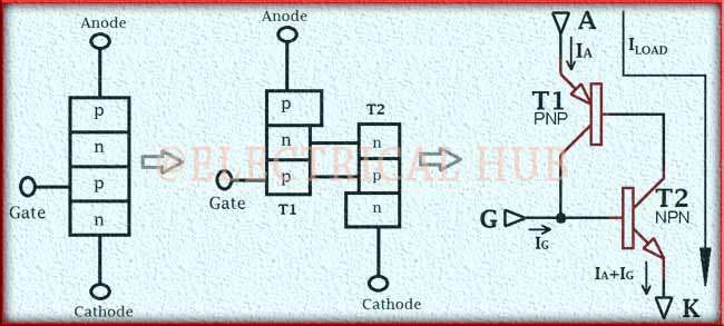
Table of Contents
How Thyristor works
To turn the thyristor on, a gate voltage is applied, typically requiring a positive pulse greater than a threshold value. Once triggered, the thyristor becomes conductive and allows a significant current to flow from the anode to the cathode. Unlike transistors, thyristors latch in the “on” state even if the gate voltage is removed.
They can only be turned off when the anode current falls below a certain level or through external means. Thyristors find application in motor control, voltage regulation, and power switching, particularly in high-power and high-voltage scenarios.
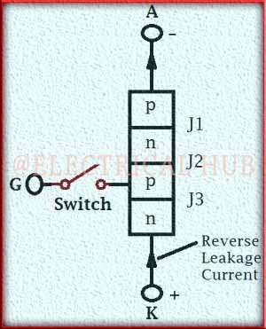
Structure: A thyristor is a three-layer semiconductor device with four layers of alternating N-type and P-type materials. It has three terminals: Anode (A), Cathode (K), and Gate (G). The main layers are the anode and cathode, with the gate acting as a control input.
Unidirectional Conduction: The thyristor is designed to allow current to flow in only one direction, from the anode to the cathode. It behaves like a diode in this regard.
Gate Triggering: The thyristor is normally non-conductive, meaning that it doesn’t allow current to pass from the anode to the cathode without any external stimulus. To turn it on, a voltage is applied to the gate terminal. When the gate voltage exceeds a certain threshold, it becomes conductive and allows current to flow.
Latching Action: Once the thyristor is triggered by the gate voltage, it remains in the conductive state even if the gate voltage is removed. This is called the latching action, and it means that it remains on until the current through it drops below a specific threshold, or until an external means (like reversing the voltage polarity) is used to turn it off.
Turn-off: To turn off a thyristor, the current through it must be reduced below a certain level (known as the holding current) or reversed in polarity. Once the current falls below this threshold, It switches off, and no more current flows through it.
Thyristors are used in a variety of applications where high-power switching is needed, such as in motor control circuits, lighting control, voltage regulation, and in some types of power supplies.
They are known for their robustness, ability to handle high currents and voltages, and their ability to maintain a state (on or off) without continuous gate control. However, they are generally not suitable for high-frequency switching applications due to their inherent turn-off time delays.
transistors analogy of thyristor
An analogy for understanding thyristors in terms of transistors can help clarify their operation. In this analogy, you can think of a thyristor as a combination of two transistors: one NPN (Negative-Positive-Negative) and one PNP (Positive-Negative-Positive) transistor.
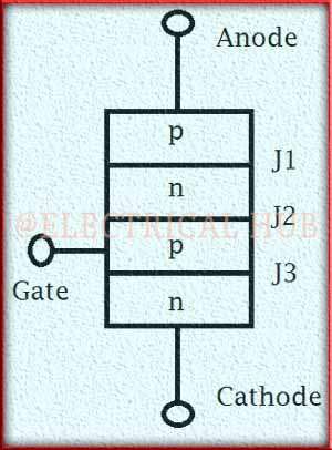
NPN Transistor: The NPN transistor has three layers of semiconductor material, just like the N-type, P-type, and N-type layers in a thyristor. In the NPN transistor, the N-type layer corresponds to the collector, the P-type layer corresponds to the base, and the N-type layer corresponds to the emitter.
PNP Transistor: The PNP transistor also has three layers, but with opposite doping compared to the NPN transistor. In the PNP transistor, the P-type layer corresponds to the collector, the N-type layer corresponds to the base, and the P-type layer corresponds to the emitter.
In a thyristor, when a voltage is applied to the gate (G), it allows a small current to flow between the anode (A) and cathode (K) terminals, similar to how a base current in a transistor allows current to flow from the collector to the emitter.
The key difference is that, unlike a transistor, once the thyristor is triggered by the gate current, it remains on even if you remove the gate current. This behavior is similar to the latching action of a thyristor, where it holds its conduction state until the anode current falls below a certain threshold or until external means are used to turn it off.
So, in short, you can think of a thyristor as a combination of two transistors (NPN and PNP) with a latching mechanism that allows it to stay on once triggered, making it suitable for high-power switching applications where transistors may not be as efficient or robust.
Thyristors Vs MOSFETs
Thyristors and MOSFETs (Metal-Oxide-Semiconductor Field-Effect Transistors) are both semiconductor devices used for switching and controlling electrical currents, but they have several key differences:
| Characteristic | Thyristor | MOSFET (Metal-Oxide-Semiconductor Field-Effect Transistor) |
| Type of Device | Semiconductor switch | Semiconductor switch |
| Control | Requires gate triggering to turn on, and external means to turn off (latching) | Controlled directly by the gate voltage (non-latching) |
| Conduction Direction | Unidirectional (current flows in one direction) | Bidirectional (current can flow in both directions) |
| Voltage Rating | Typically used for high-voltage applications | Used for a wide range of voltage applications (low to high) |
| Current Rating | Suitable for high-current applications | Suitable for both low and high-current applications |
| Switching Speed | Slower turn-on and turn-off times (microseconds to milliseconds) | Faster switching speed (nanoseconds to microseconds) |
| Turn-On and Turn-Off Control | Once triggered, it latches on until the current drops below a threshold or external means are used to turn it off | Immediate control with gate voltage (no latching) |
| Efficiency | Less efficient due to higher conduction losses | Highly efficient with low conduction losses |
| Applications | Motor control, voltage regulation, power switching in high-power systems | General-purpose switching, power amplification, low-power applications |
| Heat Generation | Generates more heat during conduction | Generates less heat during conduction |
| Gate Drive Voltage | Requires a gate voltage higher than the anode voltage for triggering | Triggered with a gate voltage lower than the drain-source voltage |
| Gate Current | Requires a gate current for triggering and holding (typically low) | Requires negligible gate current |
| Gate Protection | Not as sensitive to electrostatic discharge (ESD) damage | Sensitive to ESD and requires protection measures |
Thyristors Vs Transistors
Thyristors and transistors are both semiconductor devices, but they serve different functions and have distinct characteristics:
| Characteristic | Thyristor | Transistor |
| Function | Latches on once triggered and remains on until the current falls below a threshold or external means are used to turn it off. | Used for amplification, switching, signal processing, and voltage regulation in a wide range of electronic applications. Non-latching. |
| Control | Requires gate triggering (positive pulse) to turn on, and external means (reverse voltage or current reduction) to turn off. | Controlled by the voltage applied to the base terminal (NPN or PNP) or the gate terminal (FET) for turning on and off. |
| Conduction Direction | Unidirectional (current flows in one direction, typically from anode to cathode). | Bidirectional (current can flow in both directions). |
| Voltage Rating | Typically used in high-voltage applications. | Used across a wide range of voltage levels (low to high). |
| Current Rating | Suitable for high-current applications. | Used in both low and high-current applications. |
| Switching Speed | Slower turn-on and turn-off times (microseconds to milliseconds). | Faster switching speeds (nanoseconds to microseconds). |
| Turn-On and Turn-Off Control | Motor control, voltage regulation, and power switching in high-power systems. | Controlled immediately by the base or gate voltage (no latching). |
| Efficiency | Less efficient due to higher conduction losses. | Highly efficient with low conduction losses. |
| Applications | Motor control, voltage regulation, power switching in high-power systems. | Amplification, switching in electronic circuits, signal processing, voltage regulation. |
| Heat Generation | Generates more heat during conduction. | Generates less heat during conduction. |
| Gate (Base) Current | Requires a gate current for triggering and holding (typically low). | Requires a base current for amplification, but typically lower than gate currents in thyristors. |
| Gate (Base) Protection | Not as sensitive to electrostatic discharge (ESD) damage. | Sensitive to ESD and requires protection measures. |
V-I Characteristics of Thyristor or SCR
The V-I (Voltage-Current) characteristics of a Thyristor, also known as a Silicon-Controlled Rectifier (SCR), illustrate how the device behaves in response to changes in voltage and current.
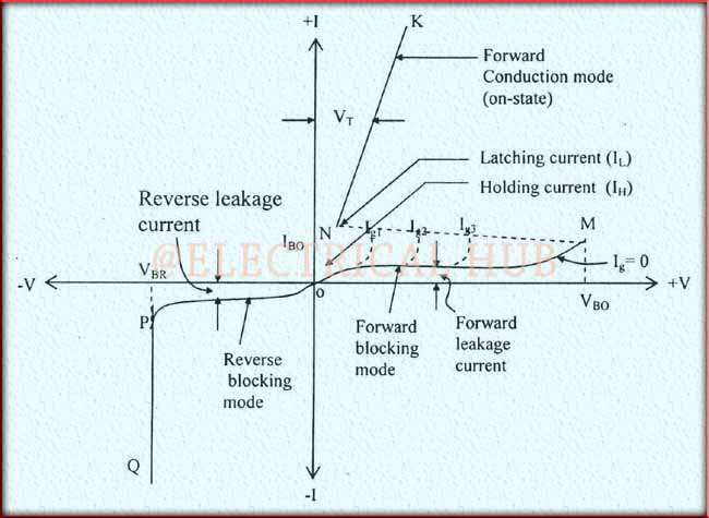
The V-I characteristics of a Thyristor typically consist of three main regions:
Forward Blocking Region (OFF State): In this region, the Thyristor is in its non-conductive or OFF state. The voltage across the Thyristor (Vak or Vd) is positive, but the current through it (Iak or Id) remains very low, typically limited to a leakage current. It does not conduct in this region.
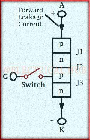
Forward Conduction Region (ON State): To trigger the Thyristor into the ON state, a gate current (Ig) must be applied. Once triggered, the Thyristor enters the forward conduction region. In this region, the Thyristor exhibits a low forward voltage drop (Vf) and allows a significant forward current (If) to flow. The device remains in the ON state until the forward current falls below a certain threshold or until external means are used to turn it off.
Reverse Blocking Region (Reverse-Biased State): When a negative voltage is applied across the Thyristor (reverse-biased), it remains non-conductive, similar to the OFF state. The reverse leakage current (Iak or Id) is very low, and the voltage remains negative (reverse blocking voltage, Vrrm, or Vdrm).
Triggering Methods of SCR or Thyristor
Silicon-controlled rectifiers (SCRs), also known as thyristors, can be triggered or turned on using various methods. The choice of triggering method depends on the specific application and requirements. Here are some common triggering methods for SCRs:
Gate Triggering (Current Triggering):
Forward Gate Triggering: This is the most common method of triggering an SCR. A positive gate current (Ig) is applied to the gate terminal of the SCR. The gate current must exceed a certain threshold called the gate trigger current (Igt) to turn the SCR on. Once triggered, the SCR remains in the ON state until the anode current falls below a certain level or until external means are used to turn it off.
Reverse Gate Triggering: In this method, a negative gate current is applied to the gate terminal. This method is less common and typically requires higher gate current levels to trigger the SCR.
Voltage Triggering:
dv/dt Triggering: In this method, the SCR is turned on by applying a rapid rate of rise of voltage (dv/dt) across the device. This method takes advantage of the SCR’s sensitivity to voltage changes. Care must be taken to control the rate of voltage rise to avoid false triggering.
di/dt Triggering: This method involves applying a rapid rate of rise of current (di/dt) to the SCR. The sudden increase in current can trigger the device. Like dv/dt triggering, di/dt triggering requires careful control to prevent unintended triggering.
Light Triggering (Optical Triggering):
Light-Activated SCR (LASCR): An LASCR is triggered by exposing it to light, typically through a light-emitting diode (LED) or laser. When the intensity of light exceeds a certain threshold, it triggers the SCR into the ON state. LASCRs find applications in optical switches and communication systems.
Temperature Triggering (Thermal Triggering):
Thermal Triggering: In rare cases, SCR triggering can occur due to a sharp temperature rise in the device. This is not a commonly used method and is typically avoided because it is less controllable.
Voltage and Current Pulse Triggering:
Pulse Triggering: SCRs can be triggered by applying a short-duration voltage or current pulse to the gate terminal. This method is used in some specialized applications.
RC Triggering (Resistor-Capacitor Triggering):
RC Triggering: An RC circuit can be used to generate a delayed gate trigger pulse. By selecting appropriate resistor and capacitor values, the timing of the trigger pulse can be controlled. This method is useful for timing applications.
The choice of triggering method depends on factors such as the desired control, sensitivity, and protection requirements of the SCR circuit. Each triggering method has its advantages and limitations, and selecting the most suitable method is crucial to ensure the reliable and safe operation of the SCR in a given application.
Follow us on LinkedIn”Electrical Insights” to get the latest updates in Electrical Engineering. You can also Follow us on LinkedIn and Facebook to see our latest posts on Electrical Engineering Topics.
Worth Read Posts

