Stator And Rotor: Important Types & Concepts
Introduction
The stator and rotor play crucial roles in the functioning of motors, generators, and other rotating machinery. Understanding these components is essential for comprehending the principles behind their operation and their applications in various industries.
Table of Contents
The stator and rotor are integral parts of electric motors and generators, working together to convert electrical energy into mechanical energy or vice versa. The stator refers to the stationary component of the device, while the rotor is the rotating part. These two elements work in harmony to enable the conversion of energy and facilitate the movement of mechanical systems.

In electric motors, the stator consists of a stationary core made up of laminated iron sheets or soft magnetic material. It is designed to provide a magnetic field that interacts with the rotor. On the other hand, the rotor is the rotating part of the motor and typically consists of a shaft, windings, and a rotor core. The rotor core is often constructed with laminated iron sheets and is responsible for producing the torque necessary for the motor’s operation.
Generators follow a similar principle, but their function is reversed. In a generator, the rotor is driven by an external force, such as a steam turbine or a gas engine, causing it to rotate within the stator. This rotation induces a magnetic field in the stator, leading to the generation of electrical energy.
The stator and rotor configuration can vary depending on the specific application and the type of motor or generator being used. For instance, in three-phase induction motors, the stator typically consists of three sets of windings placed at 120 degrees to each other, while the rotor may be squirrel-cage or wound type. Permanent magnet motors, on the other hand, have a rotor with embedded permanent magnets instead of windings.
The stator and rotor design, materials used, and the arrangement of windings all impact the efficiency, power output, and overall performance of the motor or generator. Therefore, careful consideration is given to these components during the design and manufacturing process.
The stator and rotor are vital components in electric motors, generators, and various other electromechanical devices. Their collaboration enables the conversion of electrical energy into mechanical energy or vice versa. By understanding the functions and characteristics of these components, we can appreciate their significance in the world of electromechanical engineering.
types of stator
There are several types of stators used in various applications depending on the specific requirements and design considerations.

Here are some common types of stators:
Wound Stator: This type of stator is used in many electric machines, including motors and generators. It consists of insulated wire windings wound around the stator core. The windings can be either concentrated (all coils connected together at one end) or distributed (each coil connected individually to its corresponding terminal). Wound stators allow for flexibility in design and control of the electrical characteristics of the machine.
Salient Pole Stator: This type of stator is characterized by protruding poles or teeth on the stator core. The poles create a non-uniform air gap, leading to a distinctive torque-speed characteristic. Salient pole stators are commonly used in large synchronous generators and motors where high torque at low speeds is required.
Smooth Core Stator: In contrast to the salient pole stator, the smooth core stator has a cylindrical or smooth surface without protruding poles. The absence of poles creates a uniform air gap, resulting in a more constant torque-speed characteristic. Smooth core stators are commonly used in small and medium-sized induction motors.
Permanent Magnet Stator: This type of stator incorporates permanent magnets in the stator structure. The permanent magnets create a fixed magnetic field, eliminating the need for separate stator windings. Permanent magnet stators are commonly used in brushless DC motors, where the magnets generate the necessary magnetic field for motor operation.
Hybrid Stator: A hybrid stator combines elements of different stator types to achieve specific performance objectives. For example, a hybrid stator may incorporate both wound windings and permanent magnets to combine the benefits of both technologies, such as improved efficiency and torque characteristics.
It’s important to note that the choice of stator type depends on the specific application, desired performance characteristics, and cost considerations. Each type offers its own advantages and limitations, and the selection is tailored to meet the requirements of the particular motor or generator design.
types of rotor
There are various types of rotors used in electric machines, each designed to suit specific applications and performance requirements.
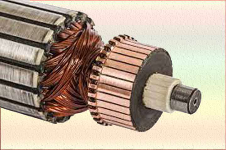
Here are some common types of rotors:
Squirrel Cage Rotor: The squirrel cage rotor is the most widely used type of rotor in induction motors. It consists of laminated iron cores and conductive bars (also known as rotor bars) that are shorted at the ends by conducting end rings. The rotor bars are typically arranged in a cylindrical or skewed configuration. When the rotating magnetic field of the stator induces a voltage in the rotor windings, current flows through the conductive bars, creating magnetic fields that interact with the stator’s magnetic field, resulting in the rotation of the rotor. The squirrel cage rotor is simple, robust, and cost-effective.
Wound Rotor: A wound rotor, also known as a slip-ring rotor, is commonly used in applications where adjustable speed control and high starting torque are required. The rotor consists of laminated iron cores and three-phase windings similar to the stator windings. Unlike a squirrel cage rotor, the rotor windings are not shorted but are connected to external resistors or slip rings. This allows for external control of the rotor’s resistance, enabling variations in speed and torque characteristics.
Salient Pole Rotor: The salient pole rotor, also called a laminated rotor, is used in synchronous generators and motors. It features rotor poles that project outward from the rotor surface, giving it a distinctive appearance. The poles are laminated to reduce eddy current losses. Salient pole rotors are typically used in low-speed applications and provide excellent torque characteristics. They are commonly found in hydroelectric generators and some large synchronous motors.
Permanent Magnet Rotor: In a permanent magnet rotor, permanent magnets are embedded or attached to the rotor surface. These magnets create a fixed magnetic field, eliminating the need for separate rotor windings. Permanent magnet rotors are commonly used in brushless DC motors, synchronous motors, and certain types of generators. They offer high efficiency, compact size, and excellent torque characteristics.
Hybrid Rotor: Hybrid rotors combine elements of different rotor types to achieve specific performance objectives. For example, a hybrid rotor may incorporate both squirrel cage bars and permanent magnets to combine the benefits of both technologies, such as improved efficiency and starting torque.
The selection of the rotor type depends on factors such as desired performance characteristics, torque requirements, control options, and cost considerations. Each rotor type has its own advantages and limitations, and the choice is tailored to meet the specific needs of the motor or generator application.
air gap between Stator and Rotor
The air gap between the stator and rotor is a crucial aspect of an electric motor’s design and operation. It refers to the physical space or distance between the outer surface of the rotor and the inner surface of the stator.
Maintaining an appropriate air gap is essential for the efficient and reliable performance of the motor. Here are a few key points regarding the air gap in an electric motor:
Magnetic Field Interaction: The air gap plays a significant role in facilitating the interaction between the magnetic fields of the stator and rotor. When electric current flows through the stator windings, a magnetic field is generated. This magnetic field induces a magnetic flux in the rotor, which causes the rotor to rotate. The air gap allows for the necessary magnetic coupling between the stator and rotor while preventing physical contact.
Influence on Motor Performance: The size of the air gap can impact the motor’s performance characteristics, such as efficiency, torque, and power output. A smaller air gap generally results in stronger magnetic coupling and higher torque generation. However, a smaller gap can also increase the risk of mechanical interference or rubbing between the stator and rotor. On the other hand, a larger air gap may reduce efficiency due to increased magnetic reluctance and reduced magnetic coupling.
Manufacturing Precision: Achieving and maintaining the desired air gap requires precise manufacturing and assembly processes. Motor manufacturers carefully control the dimensions of the stator and rotor components to ensure a uniform and consistent air gap across the entire circumference. Accurate positioning and alignment of the stator and rotor are crucial to avoid undesirable variations in the air gap.
Maintenance Considerations: Over time, wear and tear, or other factors can affect the air gap in a motor. Excessive wear or physical damage to the rotor or stator can result in an irregular air gap, leading to decreased motor performance, increased noise, and potential mechanical issues. Regular inspection and maintenance are necessary to detect and rectify any issues with the air gap.
The air gap between the stator and rotor in an electric motor is a critical parameter that affects the motor’s performance and efficiency. It enables the necessary magnetic interaction between the stator and rotor while maintaining physical separation. Proper control, maintenance, and monitoring of the air gap are essential for optimal motor operation and longevity.
relative speed between stator and rotor fluxes
The relative speed between the stator and rotor fluxes is an important concept in rotating electrical machines such as motors and generators. It refers to the speed difference between the magnetic fields produced by the stator and rotor components.
In an induction motor, for example, the stator’s rotating magnetic field induces currents in the rotor, which in turn creates a magnetic field of its own. The rotor magnetic field tries to catch up with the rotating stator field, but due to the slip, which is the relative speed between the stator and rotor, the rotor field lags behind the stator field.
The slip is expressed as a percentage of the difference between the synchronous speed and the actual rotor speed, with the synchronous speed being the speed at which the rotating magnetic field would travel if there were no slip. The slip is influenced by factors such as the mechanical load on the motor and the design characteristics of the motor itself.
In a synchronous generator or motor, the relative speed between the stator and rotor fluxes is zero, as the rotor rotates at the same speed as the rotating magnetic field produced by the stator. This synchronism is maintained through various control mechanisms such as excitation systems or frequency synchronization.
The relative speed between the stator and rotor fluxes directly affects the operation and performance of electrical machines. It determines the torque production in motors and the induced voltage in generators. By controlling the slip or maintaining synchronous operation, the speed and efficiency of the machine can be regulated.
The relative speed between the stator and rotor fluxes, often referred to as slip in induction motors, is the speed difference between the rotating magnetic fields produced by the stator and rotor components. It influences the torque generation and overall performance of motors and generators. Maintaining appropriate slip or synchronous operation is crucial for optimal operation and control of rotating electrical machines.
Stator and Rotor in aC generator
In an AC generator, the stator and rotor are key components responsible for generating alternating current (AC) electricity. The stator and rotor work together to produce a rotating magnetic field, which induces the generation of electrical energy.
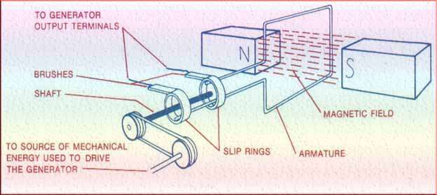
The stator in an AC generator is the stationary part of the device. It consists of a core made up of laminated iron sheets or soft magnetic material. The stator core is designed with slots that house the stator windings. These windings are typically three-phase windings, arranged at specific angles to each other (often 120 degrees apart in a three-phase system). When an alternating current flows through these windings, it creates a magnetic field that remains stationary due to the fixed position of the stator.
The rotor, on the other hand, is the rotating part of the AC generator. It is connected to a shaft and is responsible for creating the magnetic field that interacts with the stator’s windings. The rotor can have different designs depending on the type of AC generator. One common type of rotor is the wound rotor, which consists of three sets of windings connected to slip rings.
The windings are usually made of copper and are connected to an external load, allowing the flow of current. Another type of rotor is the squirrel-cage rotor, which consists of conductive bars shorted together at the ends. As the rotor rotates, the magnetic field induced by the stator windings interacts with the rotor, causing the flow of current in the windings.
The interaction between the rotating magnetic field of the rotor and the stationary magnetic field of the stator induces an electromotive force (EMF) in the stator windings. This EMF creates an alternating current, which can be extracted from the generator’s terminals and used to power electrical devices.
The stator and rotor configuration, as well as the design of the windings, determine the generator’s voltage, power output, and frequency. By controlling the excitation of the rotor and the speed of rotation, the AC generator can produce electricity with different characteristics to meet various power requirements.
The stator and rotor are essential components in an AC generator. The stator provides the stationary magnetic field through its windings, while the rotor creates a rotating magnetic field that interacts with the stator’s field. This interaction induces the generation of alternating current, which can be harnessed and utilized for various applications.
Stator and Rotor in dC generator
In a DC generator, the stator and rotor are essential components responsible for generating direct current (DC) electricity. These components work together to produce a constant and unidirectional flow of electrical energy.
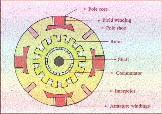
The stator in a DC generator is the stationary part of the device. It consists of a core made up of laminated iron sheets or soft magnetic material. The stator core is designed with slots to house the stator windings. The windings are typically made of copper wire and are connected in a specific pattern to create multiple poles. When direct current flows through these windings, a stationary magnetic field is established.
The rotor, on the other hand, is the rotating part of the DC generator. It is connected to a shaft and is responsible for creating a magnetic field that interacts with the stator’s magnetic field. The rotor can have different designs depending on the type of DC generator. One common type of rotor is the wound rotor, which consists of windings connected to a commutator.
The commutator is a cylindrical structure with segments that are insulated from each other. Brushes, typically made of carbon or graphite, are in contact with the commutator segments. As the rotor rotates, the windings and the commutator cause the flow of current to be reversed periodically, resulting in a unidirectional current at the generator’s output terminals.
When the rotor rotates, the interaction between the magnetic field of the stator and the rotor’s magnetic field induces an electromotive force (EMF) in the stator windings. This EMF creates a direct current that can be extracted from the generator’s terminals and used to power electrical devices.
The stator and rotor configuration, as well as the design of the windings and commutator, determine the generator’s voltage, power output, and efficiency. By controlling the excitation of the rotor and the speed of rotation, the DC generator can produce a consistent and regulated flow of direct current.
The stator and rotor are crucial components in a DC generator. The stator provides the stationary magnetic field through its windings, while the rotor, through its rotating magnetic field and commutator, generates a unidirectional current. Together, these components enable the conversion of mechanical energy into direct current electricity, making DC generators suitable for various applications where a constant and controlled flow of current is required.
Stator and Rotor in motor
In an electric motor, the stator and rotor are fundamental components that work in harmony to convert electrical energy into mechanical energy. These components are essential for the motor’s operation and determine its performance characteristics.
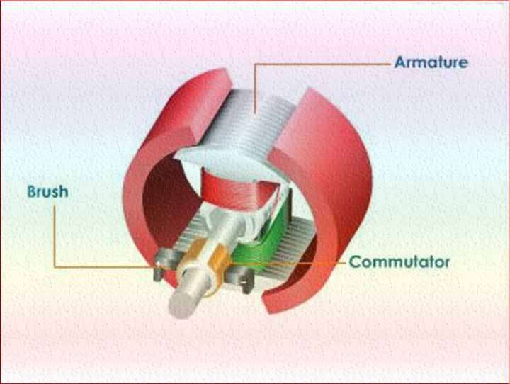
The stator in an electric motor is the stationary part of the device. It typically consists of a core made of laminated iron sheets or soft magnetic material. The stator core is designed with slots to hold the stator windings. These windings are often made of copper wire and are arranged in a specific pattern, such as multiple phases or poles, depending on the motor type. The stator windings are connected to an external power supply and carry the electrical current that creates a magnetic field.
The rotor, on the other hand, is the rotating part of the electric motor. It is mounted on a shaft and positioned inside the stator. The rotor can have various designs depending on the motor type. In most motors, the rotor consists of a core made of laminated iron sheets and conductive bars or coils. The conductive elements can be either a squirrel-cage rotor or a wound rotor. In a squirrel-cage rotor, the conductive bars are shorted at the ends, forming a closed loop. In a wound rotor, the conductive coils are connected to external resistors or a separate power source.
When the electric motor is powered, an alternating current (AC) or direct current (DC) is applied to the stator windings, creating a magnetic field. This magnetic field interacts with the rotor, inducing a force that causes the rotor to rotate. As the rotor rotates, it produces mechanical torque that drives the motor’s intended application, such as rotating a fan blade or propelling a vehicle.
The stator and rotor configuration, the number of poles, and the arrangement of windings determine the motor’s speed, torque, and efficiency. Various types of electric motors exist, including induction motors, synchronous motors, and brushed or brushless DC motors. Each motor type utilizes different stator and rotor designs to optimize its performance for specific applications.
In summary, the stator and rotor are integral components of an electric motor. The stator provides the stationary magnetic field through its windings, while the rotor interacts with this magnetic field to generate mechanical rotation. Together, the stator and rotor enable the conversion of electrical energy into mechanical energy, powering a wide range of devices and machinery.
Stator and Rotor in induction motor
In an induction motor, the stator and rotor are critical components that enable the motor to operate and convert electrical energy into mechanical energy. Induction motors are the most commonly used type of electric motors, found in a wide range of applications such as industrial machinery, appliances, and HVAC systems.
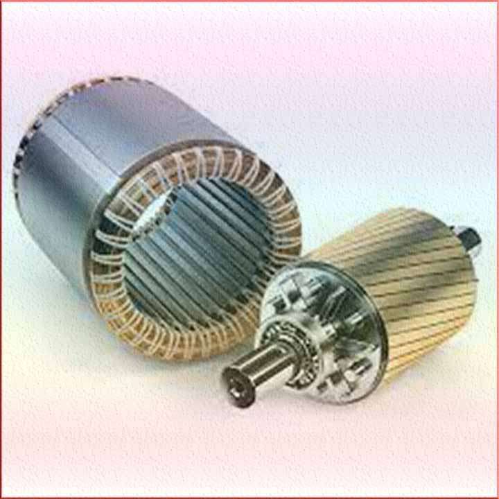
The stator in an induction motor is the stationary part of the device. It consists of a stator core made of laminated iron sheets and stator windings. The stator windings are typically arranged in a three-phase configuration, producing a rotating magnetic field when energized with three-phase AC power. The stator windings are evenly distributed in the stator slots to ensure a balanced magnetic field.
The rotor in an induction motor is the rotating part that interacts with the stator’s magnetic field to produce mechanical torque. There are two main types of rotors used in induction motors: squirrel-cage rotors and wound rotors.
A squirrel-cage rotor is the most common type and consists of laminated iron cores and conductive bars or “shorted” rotor windings. The conductive bars are arranged in a cylindrical or skewed configuration and connected at both ends by shorting rings. When the rotating magnetic field of the stator induces a voltage in the rotor windings, current flows through the conductive bars, creating magnetic fields that interact with the stator’s magnetic field, resulting in the rotation of the rotor.
A wound rotor, also known as a slip-ring rotor, consists of a laminated iron core with three-phase windings similar to the stator windings. However, instead of being directly shorted like in a squirrel-cage rotor, the rotor windings are connected to external resistors or slip rings. This allows for external control of the rotor’s resistance and, consequently, its speed and torque characteristics.
When power is supplied to the stator windings, a rotating magnetic field is generated, which induces currents in the rotor windings. These currents create a magnetic field in the rotor that interacts with the stator’s magnetic field, producing a torque that drives the rotor’s rotation.
The design and characteristics of the stator and rotor in an induction motor impact its performance, efficiency, and operating characteristics. Factors such as the number of stator slots, rotor bar configuration, and the quality of materials used influence the motor’s speed, torque, and ability to handle different loads.
In summary, the stator and rotor are essential components of an induction motor. The stator generates a rotating magnetic field through its windings, while the rotor interacts with this magnetic field, producing mechanical rotation. Together, these components allow the induction motor to convert electrical energy into mechanical energy, making it a versatile and widely used motor in various industrial and domestic applications.
Stator and Rotor in Turbine
In a turbine, the stator and rotor are key components that play vital roles in the conversion of fluid or gas energy into mechanical energy. Turbines are widely used in power generation, propulsion systems, and various industrial applications.
The stator and rotor in a turbine work together to extract energy from a flowing fluid or gas and convert it into rotational motion.
The stator is the stationary component of the turbine. It consists of a series of fixed blades or vanes arranged in a ring or annular structure. The stator blades are designed to direct and control the flow of the fluid or gas passing through the turbine. They serve to change the direction and velocity of the fluid, preparing it for interaction with the rotor.
The rotor, also known as the turbine wheel, is the rotating component of the turbine. It consists of a disc or wheel with a series of curved blades attached to it. The rotor blades are aerodynamically shaped to efficiently capture the energy of the fluid or gas. As the fluid or gas passes over the rotor blades, it imparts a force that causes the rotor to rotate.
The interaction between the stator and rotor blades is crucial for the functioning of the turbine. As the fluid or gas flows through the stator blades, it undergoes a change in velocity and pressure. This controlled flow then enters the rotor blades, where the high-velocity fluid or gas applies a force on the blades, causing the rotor to rotate.
The rotation of the rotor is utilized to drive various types of machinery or generate electricity. In power generation, the rotating rotor is connected to a generator, where the mechanical energy is converted into electrical energy. In propulsion systems, such as gas turbines used in aircraft engines, the rotational motion of the rotor is harnessed to provide thrust and propulsion.
The design and configuration of the stator and rotor blades vary depending on the specific application and type of turbine. For example, in steam turbines, the stator and rotor blades are designed to accommodate the characteristics of high-pressure steam flow. Gas turbines, on the other hand, are designed to handle the flow of combustion gases.
The stator and rotor are integral components in a turbine. The stator directs and controls the flow of fluid or gas, while the rotor captures the energy from the flow and converts it into rotational motion. Together, these components enable the conversion of fluid or gas energy into useful mechanical work, making turbines essential in various industries and applications.
Follow us on LinkedIn“Electrical Insights” to get the latest updates in Electrical Engineering. You can also Follow us LinkedIn to see our latest posts.
Frequently asked Questions
What is a stator and rotor?
A stator is a stationary component in an electric motor or generator that contains coils of wire to produce a magnetic field. A rotor, on the other hand, is a rotating component that interacts with the stator’s magnetic field to generate mechanical energy.
What is the role of the stator and rotor in an electric motor?
The stator’s role is to produce a magnetic field when electric current flows through its coils, while the rotor’s role is to convert the magnetic field into mechanical energy by rotating within the stator’s field.
How do the stator and rotor interact with each other in a motor?
The stator’s magnetic field induces a magnetic force on the rotor, causing it to rotate. This interaction between the magnetic fields of the stator and rotor generates the rotational motion in an electric motor.
What are the key differences between the stator and rotor?
The stator is stationary, while the rotor rotates. The stator typically consists of coils of wire, while the rotor often contains permanent magnets or windings. Additionally, the stator is responsible for creating the magnetic field, while the rotor converts it into mechanical energy.
What materials are commonly used to manufacture stators and rotors?
Stators are commonly made from laminated steel cores to provide high magnetic permeability and reduce energy losses. Rotors can be made of various materials, such as laminated steel, copper, or aluminum, depending on the motor’s design and application.
How does the design of the stator and rotor affect the performance of an electric motor?
The design of the stator and rotor influences factors like motor efficiency, power output, torque, and speed characteristics. Factors such as the number of stator and rotor poles, coil arrangement, core materials, and rotor design contribute to the overall performance of an electric motor.
Can the stator and rotor be replaced or repaired in case of damage?
In most cases, damaged stators and rotors can be repaired or replaced. However, the feasibility of repair or replacement depends on the extent of the damage, the motor’s design, and the availability of suitable replacement parts. Professional assessment and expertise are often required to determine the best course of action.


