ESP32S Pinout: Pin Configuration and Layout
Introduction to ESP32S Pinout and Configuration
The ESP32S has revolutionized the world of embedded systems and IoT development. Understanding the ESP32S pinout is crucial for developers and hobbyists alike who want to make the most of this powerful microcontroller. In this comprehensive guide, we’ll explore everything you need to know about the ESP-WROOM-32 pinout and its various applications.
Table of Contents

Understanding ESP32S Pinout Configuration
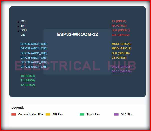
The ESP32-WROOM-32 pinout features a robust arrangement of 38 pins that provide extensive functionality for diverse applications. This development board offers an impressive combination of digital, analog, and special-purpose pins that make it a versatile choice for IoT projects.
Key Features of ESP32S Pin Layout
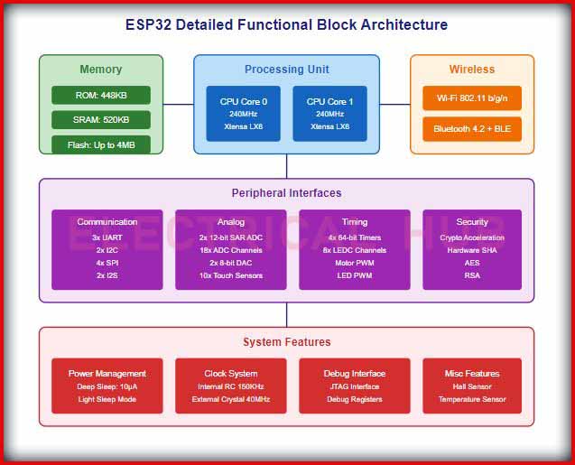
- Dual-core processor operating at 240MHz
- Integrated Wi-Fi and Bluetooth capabilities
- Rich peripheral interface support
- Multiple power supply pins
- Dedicated GPIO pins
- Specialized communication interfaces
ESP32 Development Board Pinout Overview
The ESP32 dev board pinout includes several essential components:
- Power Pins
- 3.3V output pins
- 5V input pin
- Multiple ground (GND) pins
- EN (Enable) pin
- USB to UART Bridge
- TX (GPIO1)
- RX (GPIO3)
- General Purpose Input/Output (GPIO) Pins
- 34 programmable GPIO pins
- Support for various protocols
- Analog-to-Digital Conversion (ADC) capability
ESP32 Advanced Functional Block Diagram

Detailed ESP32S Pinout Diagram Analysis
The ESP32 pin diagram can be broken down into several functional groups:
Power and Control Pins
- VIN: Input voltage (5V)
- 3.3V: Regulated output voltage
- GND: Ground connections
- EN: Reset/Enable pin
Communication Interface Pins
- UART: GPIO1 (TX) and GPIO3 (RX)
- I2C: GPIO21 (SDA) and GPIO22 (SCL)
- SPI: GPIO23 (MOSI), GPIO19 (MISO), GPIO18 (SCK)
- CAN: GPIO4 and GPIO5
Special Function Pins
- ADC Pins: GPIO32-GPIO39
- DAC Pins: GPIO25 and GPIO26
- Touch Sensor Pins: GPIO4, GPIO0, GPIO2, GPIO15
- Hall Sensor: GPIO36 and GPIO39
Applications Using ESP32 Board Pinout
The ESP32S pinout configuration enables numerous applications:
- IoT Projects
- Smart home automation
- Environmental monitoring
- Industrial control systems
- Wearable technology
- Communication Systems
- Wi-Fi applications
- Bluetooth devices
- Mesh networking
- Remote sensing
- Display Integration
- LCD interfaces
- OLED displays
- TFT screens
- LED matrix control
Technical Specifications of ESP32-WROOM-32 Pinout
The ESP32 pinout 38 pin configuration includes:
- Operating voltage: 3.3V
- Input voltage range: 2.3V to 3.6V
- Maximum current per GPIO: 40mA
- Flash memory: up to 4MB
- SRAM: 520KB
- Clock speed: up to 240MHz
Best Practices for ESP32S Pin Usage
When working with the ESP32 pin layout, consider these guidelines:
- Power Management
- Always use appropriate voltage levels
- Include decoupling capacitors
- Monitor power consumption
- GPIO Configuration
- Check pin states during boot
- Use pull-up/pull-down resistors when necessary
- Avoid floating inputs
- Interface Design
- Consider signal integrity
- Implement proper grounding
- Use appropriate protection circuits
Common Troubleshooting Tips
When working with the ESP32 development board pinout:
- Check voltage levels regularly
- Verify pin assignments in code
- Monitor serial communication
- Test GPIO functionality
- Validate peripheral connections
Conclusion
Understanding the ESP32S pinout is essential for successful project implementation. Whether you’re working with the ESP-WROOM-32 pinout or the standard ESP32 pin diagram, this comprehensive guide provides the necessary information for your development needs. The versatility and robust feature set of the ESP32 board pinout make it an excellent choice for various applications, from simple IoT projects to complex embedded systems.
Remember to refer to the official ESP32 pinout diagram and documentation when designing your projects, and always follow proper electrical design practices to ensure reliable operation of your devices.
Worth Read Posts
Follow us on LinkedIn”Electrical Insights” to get the latest updates in Electrical Engineering. You can also Follow us on LinkedIn and Facebook to see our latest posts on Electrical Engineering Topics.


Very nice post. I absolutely love this website. Continue the good work!