Cathode Ray Oscilloscope(CRO) Working and Important Applications
Introduction
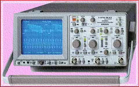
A cathode ray oscilloscope (CRO), also known as an oscilloscope or scope, is a widely used electronic test instrument that allows you to visualize electrical waveforms. It is particularly useful in the field of electronics, telecommunications, and physics for observing and analyzing various types of electrical signals.
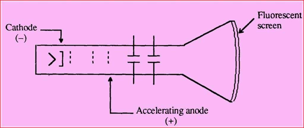
The fundamental component of a CRO is a cathode ray tube (CRT). The CRT consists of an electron gun that emits a narrow beam of electrons, which are accelerated and focused by an electric field. The electron beam then strikes a fluorescent screen, causing it to emit light at the point of impact. By controlling the horizontal and vertical deflection of the electron beam, the CRO can display a two-dimensional representation of the input signal on the screen.
Table of Contents
Here are some key features and uses of a cathode ray oscilloscope:
Display: The CRO displays voltage as a function of time, with voltage represented on the vertical axis and time on the horizontal axis. This allows you to visualize waveforms such as sine waves, square waves, pulses, and more complex signals.
Timebase: The timebase control determines the speed at which the horizontal sweep moves across the screen, thus controlling the time scale of the displayed waveform. This allows you to observe both high-frequency and low-frequency signals.
Vertical Amplifier: The vertical amplifier controls the sensitivity of the CRO to voltage changes. It allows you to adjust the vertical scale and position of the waveform on the screen.
Triggering: The triggering function allows you to stabilize repetitive waveforms by initiating the sweep at a specific point in the waveform. It helps in capturing and displaying stable waveforms on the screen.
Measurement: CROs often have built-in measurement features such as voltage and time measurements, frequency analysis, and other parameters that aid in waveform analysis and troubleshooting.
Probes: CROs are typically used with probes, which are connected to the input terminals of the oscilloscope. Probes allow you to safely measure signals without affecting the circuit being tested.

Working of cathode ray oscilloscope
The working principle of a cathode ray oscilloscope (CRO) involves several key components and processes. Here’s a step-by-step explanation of how a CRO operates:
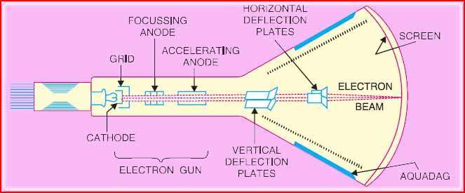
Electron Beam Generation: The CRO starts with an electron gun, which emits a narrow beam of electrons. The electron gun consists of a cathode, which emits electrons when heated, and control grids that focus and accelerate the electrons.

Electron Beam Deflection: Once emitted, the electron beam passes through a set of deflection plates—one for horizontal deflection (X-axis) and another for vertical deflection (Y-axis). These deflection plates are connected to the input signal being measured.
Horizontal Deflection: The horizontal deflection plates receive a time-varying voltage signal known as the timebase signal. This signal controls the rate at which the electron beam moves horizontally across the screen. By adjusting the timebase settings, you can control the time scale at which the waveform is displayed.
Vertical Deflection: The vertical deflection plates receive the input signal being measured. This signal is connected to the vertical amplifier of the CRO. The vertical amplifier amplifies the input signal and provides the necessary voltage to deflect the electron beam vertically. The amplitude of the input signal determines the vertical deflection of the electron beam on the screen.
Display: The electron beam, after being deflected both horizontally and vertically, reaches the fluorescent screen located at the end of the cathode ray tube (CRT). The fluorescent screen emits light when struck by the electron beam, producing a visible spot or trace on the screen.
Trace Persistence: The CRO typically has a trace persistence feature that keeps the displayed waveform visible for a short period. This persistence allows you to see multiple waveforms superimposed on each other, providing a clearer representation of the signal.
Triggering: Triggering is used to stabilize repetitive waveforms on the screen. The trigger circuitry detects a specific point or event on the input signal and initiates the horizontal sweep of the electron beam. This ensures that the waveform appears stationary on the screen, making it easier to analyze and measure.
Controls and Measurements: CROs have various controls and features that allow you to adjust the vertical and horizontal scales, position the waveform on the screen, measure voltage levels, calculate time intervals, and perform other measurements and analysis on the displayed waveform.
By adjusting the settings and controls of a CRO, you can observe and analyze various types of signals, including periodic waveforms, transients, pulses, and complex waveforms. The CRO provides a visual representation of these signals, enabling you to measure, troubleshoot, and understand the behavior of electrical waveforms in different applications.

Components of cathode ray oscilloscope
A cathode ray oscilloscope (CRO) consists of several key components that work together to generate and display waveforms. Here are the main components of a CRO:
Cathode Ray Tube (CRT): The CRT is a vacuum tube at the heart of the oscilloscope. It includes an electron gun that emits a focused beam of electrons and a fluorescent screen that emits light when struck by the electron beam. The CRT is responsible for creating the visual display of the waveform.
Electron Gun: The electron gun is located within the CRT and consists of a cathode and one or more control grids. The cathode emits electrons when heated, and the control grids help focus and accelerate the electrons into a narrow beam.
Deflection Plates: The deflection plates are positioned near the CRT and are responsible for deflecting the electron beam. There are typically two sets of deflection plates: vertical plates (Y-axis) and horizontal plates (X-axis). The input signal is connected to the deflection plates to control the positioning of the electron beam on the screen.
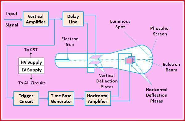
Vertical Amplifier: The vertical amplifier amplifies the input signal that is connected to the vertical deflection plates. It adjusts the amplitude of the signal and provides the necessary voltage to deflect the electron beam vertically on the screen.
Horizontal Amplifier and Timebase: The horizontal amplifier amplifies the timebase signal, also known as the sweep signal or time sweep, which controls the horizontal deflection of the electron beam. The timebase determines the time scale at which the waveform is displayed on the screen.
Trigger Circuit: The trigger circuit is responsible for initiating the horizontal sweep of the electron beam at a specific point or event in the input signal. It helps stabilize repetitive waveforms on the screen by ensuring that the waveform starts at the same position.
Display: The display is the visible part of the oscilloscope where the waveform is shown. It consists of the fluorescent screen located at the end of the CRT. When the electron beam strikes the screen, it emits light, creating a visible trace or spot that represents the waveform.
Control Panel: The control panel is where the user interacts with the oscilloscope. It contains various knobs, buttons, and switches to adjust settings such as vertical sensitivity, horizontal time scale, trigger level, and waveform positioning. The control panel allows the user to customize the display and measurement parameters.
Additionally, modern CROs may have additional features and components such as digital signal processing, memory, advanced triggering options, measurement capabilities, and interfaces for connecting to external devices or computers.
These components work together to capture, amplify, deflect, and display electrical waveforms on the screen, enabling the user to observe, measure, and analyze signals in various applications.
Block Diagram of Cathode Ray Oscilloscope

Types of cathode ray oscilloscope
There are several types of cathode ray oscilloscope that have been developed over the years. Here are some common types:
Analog Oscilloscope: Analog CROs were the earliest type of oscilloscopes and are based on analog electronics. They use an analog CRT and analog circuitry to generate and display waveforms. Analog CROs provide real-time waveform display and are known for their smooth and continuous trace. They are still used in many applications due to their simplicity and affordability.
Digital Storage Oscilloscope (DSO): Digital storage oscilloscopes are a more advanced type of oscilloscope that use digital technology for signal acquisition and processing. DSOs convert the input signal into digital form using an analog-to-digital converter (ADC), allowing for storage and processing of waveforms.
They can capture and store waveforms for later analysis, offer advanced triggering options, and provide a range of measurement and analysis functions. DSOs are widely used in various fields due to their versatility and ability to handle complex signals.
Digital Phosphor Oscilloscope (DPO): Digital phosphor oscilloscopes combine the features of DSOs and analog CROs. They use digital processing techniques along with a special phosphor screen on the CRT to provide a color-coded persistence display. DPOs offer enhanced waveform visualization and analysis capabilities, allowing for better insight into complex and dynamic signals.
Mixed Signal Oscilloscope (MSO): Mixed signal oscilloscopes combine analog and digital channels in a single instrument. They are designed to capture and display both analog and digital signals simultaneously. MSOs are particularly useful for debugging and analyzing digital circuits and systems, as they can correlate analog and digital signals and provide a comprehensive view of the system behavior.
PC-Based Oscilloscope: PC-based oscilloscopes leverage the processing power and display capabilities of a computer or laptop. These oscilloscopes typically consist of a hardware interface that connects to the computer’s USB or Ethernet port, and the waveform acquisition and analysis are performed using software running on the computer. PC-based oscilloscopes offer flexibility, portability, and often provide advanced features similar to DSOs.
Handheld Oscilloscope: Handheld oscilloscopes are compact, portable devices designed for on-the-go use. They usually have a smaller form factor, built-in display, and battery power. Handheld oscilloscopes are handy for field technicians, service personnel, and anyone who requires a portable oscilloscope for quick measurements and troubleshooting.
Each type of oscilloscope has its advantages and is suited for different applications and user requirements. The choice of the oscilloscope type depends on factors such as the nature of the signals to be measured, required features and performance, portability, and budget.
applications of cathode ray oscilloscope
Cathode ray oscilloscope (CROs) have numerous applications across various fields. Here are some common applications of CROs:
Electronics and Circuit Analysis: Cathode ray oscilloscope is extensively used in electronics and circuit analysis to visualize and measure electrical waveforms. They allow engineers and technicians to observe signals at different points in a circuit, identify abnormalities, measure voltage levels, verify signal timing, and analyze waveforms for troubleshooting and circuit design.
Signal Verification: Cathode ray oscilloscope is used to verify the integrity of electrical signals in a wide range of applications. They can detect and display waveforms such as sine waves, square waves, pulses, and more complex signals. By observing the signal on the CRO screen, you can ensure that the signal meets the desired specifications and quality standards.
Time Domain Analysis: Cathode ray oscilloscopes are excellent tools for analyzing signals in the time domain. They can help determine the duration, frequency, rise time, fall time, pulse width, and other timing parameters of electrical signals. This is particularly useful for analyzing digital signals, measuring signal delays, and investigating signal distortions.
Frequency Analysis: Cathode ray oscilloscopes can also perform frequency domain analysis using Fourier transform techniques. By applying the Fast Fourier Transform (FFT) algorithm to the input signal, the CRO can display the frequency spectrum of the signal. This allows you to identify the frequency components, harmonics, noise, and modulation present in the signal.
Waveform Generation and Testing: Some Cathode ray oscilloscopes come equipped with a built-in waveform generator that can produce various waveforms, such as sine waves, square waves, and triangular waves. This feature allows you to generate specific signals for testing purposes, such as evaluating the frequency response of a circuit or simulating specific waveform conditions.
Communication Systems: Cathode ray oscilloscopes are employed in the analysis and troubleshooting of communication systems. They can be used to measure signal distortion, assess the quality of transmitted signals, analyze modulation schemes, observe radio frequency (RF) signals, and investigate issues in audio and video transmission.
Power Electronics: Cathode ray oscilloscopes find applications in power electronics for analyzing and measuring waveforms in power circuits, such as inverters, rectifiers, and motor drives. They assist in examining voltage and current waveforms, observing switching behavior, analyzing power factor, and studying transient responses.
Education and Research: Cathode ray oscilloscopes are widely used in educational institutions and research laboratories for teaching and experimental purposes. They allow students and researchers to understand and study various electrical phenomena, perform experiments, validate theoretical concepts, and visualize real-time signals in different fields of study, including physics, electronics, telecommunications, and engineering.
It’s important to note that while traditional analog Cathode ray oscilloscopes have been widely used, digital oscilloscopes (DSOs) with advanced features and capabilities have become more prevalent. DSOs offer additional functionalities, including signal storage, advanced triggering options, waveform analysis, and integration with computer systems for data processing and automation.
benefits of cathode ray oscilloscope
Cathode ray oscilloscopes (CROs) offer several benefits that make them indispensable tools in various fields. Here are some key advantages of using a Cathode ray oscilloscope:
Visualization of Waveforms: CROs provide a visual representation of electrical waveforms, allowing you to observe the shape, amplitude, frequency, and timing of signals in real-time. This visual feedback is invaluable for understanding the behavior of electronic circuits and troubleshooting issues.
Time Domain Analysis: Cathode ray oscilloscopes excel at time domain analysis, enabling you to measure and analyze parameters such as rise time, fall time, pulse width, period, and frequency. This capability is essential for assessing signal quality, identifying timing issues, and detecting abnormalities in waveforms.
Measurement and Analysis: Cathode ray oscilloscopes offer various measurement functions, including voltage measurements, time measurements, amplitude calculations, and frequency analysis. They allow you to make accurate and precise measurements of signals, aiding in circuit characterization, performance evaluation, and fault diagnosis.
High-Speed Signal Capture: Cathode ray oscilloscopes can capture and display high-speed signals with rapid rise and fall times. They have the ability to capture transients, glitches, and fast-changing waveforms, which can be challenging for other measurement instruments. This makes CROs well-suited for analyzing high-frequency signals and digital communication systems.
Triggering and Stability: CROs incorporate triggering capabilities that enable stable waveform display. By setting the trigger level and trigger mode, you can stabilize repetitive waveforms, capture specific events, and observe the same portion of the waveform consistently. Triggering ensures that the displayed waveform remains steady and repeatable, facilitating accurate analysis and measurement.
Real-Time Observation: Cathode ray oscilloscopes provide immediate, real-time observation of signals, making them ideal for dynamic and time-varying phenomena. This real-time feedback allows you to quickly assess changes in signals, identify anomalies, and validate the performance of circuits or systems.
Educational Tool: CROs are widely used in educational settings as essential teaching tools. They help students visualize and understand abstract concepts related to electronics, physics, and telecommunications. Cathode ray oscilloscopes facilitate hands-on learning, allowing students to observe and analyze real-world signals and gain practical skills in waveform interpretation and measurement.
Versatility and Flexibility: Cathode ray oscilloscopes are versatile instruments that can be used across a wide range of applications. They can measure and analyze various types of signals, including analog, digital, audio, video, and RF signals. Additionally, CROs can be combined with other instruments and accessories, such as signal generators and probes, to expand their functionality and measurement capabilities.
Cathode ray oscilloscopes have been a fundamental tool in electronics and related fields for many decades due to their ability to provide valuable insights into electrical waveforms. While digital oscilloscopes have become more prevalent in recent years, CROs still offer unique benefits and continue to be widely used in many applications.
Conclusion
In conclusion, cathode ray oscilloscopes (CROs) are versatile and essential tools in the field of electronics and signal analysis. They offer several advantages that make them invaluable for observing, measuring, and analyzing electrical waveforms. Here are the key points about Cathode ray oscilloscopes:
Visualization: CROs provide a visual representation of waveforms, allowing users to observe the shape, amplitude, frequency, and timing of signals in real-time. This visual feedback is crucial for understanding circuit behavior and troubleshooting issues.
Time Domain Analysis: Cathode ray oscilloscopes excel at time domain analysis, enabling measurement and analysis of parameters such as rise time, fall time, pulse width, period, and frequency. This capability helps assess signal quality, identify timing issues, and detect abnormalities in waveforms.
Measurement and Analysis: CROs offer a wide range of measurement functions and analysis capabilities. They allow for accurate and precise voltage measurements, time measurements, amplitude calculations, and frequency analysis.
High-Speed Signal Capture: Cathode ray oscilloscopes can capture and display high-speed signals with rapid rise and fall times. They are capable of capturing transients, glitches, and fast-changing waveforms, making them ideal for analyzing high-frequency signals and digital communication systems.
Real-Time Observation: CROs provide immediate, real-time observation of signals, allowing for quick assessment of changes, identification of anomalies, and validation of circuit or system performance.
Triggering and Stability: Cathode ray oscilloscopes incorporate triggering capabilities to stabilize repetitive waveforms and ensure consistent display. Triggering allows for precise and repeatable waveform observation, facilitating accurate analysis and measurement.
Educational Tool: CROs are widely used in educational settings as teaching tools. They help students visualize and understand abstract concepts in electronics, physics, and telecommunications. Cathode ray oscilloscopes enable hands-on learning and practical waveform interpretation and measurement skills.
While digital oscilloscopes have gained popularity, CROs continue to offer unique benefits. They provide valuable insights into electrical waveforms and remain widely used in various applications. Whether in the lab, field, or classroom, Cathode ray oscilloscopes play a vital role in signal analysis, troubleshooting, and understanding the behavior of electronic systems.
Frequently Asked Questions
What is a cathode ray oscilloscope?
A cathode ray oscilloscope (CRO) is an electronic test instrument used to display and analyze the waveform of electrical signals. It utilizes a cathode ray tube (CRT) to generate and display the waveforms on a screen.
What is cathode ray oscilloscope and its uses?
A cathode ray oscilloscope is a device used to visualize and measure electrical signals in various applications. It is commonly used in electronics, telecommunications, engineering, and scientific research to analyze waveforms, measure voltage, frequency, and time intervals, troubleshoot circuits, and more.
What are the basics of CRO?
The basics of a cathode ray oscilloscope involve the generation of an electron beam in a CRT, which is deflected to form a waveform on a phosphor-coated screen. The vertical deflection represents the amplitude of the signal, and the horizontal deflection represents time. The CRO also includes controls for adjusting voltage scales, timebase settings, triggering, and waveform measurements.
What is cathode ray function?
The function of the cathode ray in a cathode ray oscilloscope is to generate a focused beam of electrons that can be deflected by electric fields. This deflection allows the beam to trace the waveform of an input signal onto the screen of the oscilloscope.
What is the use of an oscilloscope?
An oscilloscope is used to observe and analyze electrical waveforms, measure voltage levels, frequencies, and time intervals, troubleshoot circuit problems, verify signal integrity, characterize electronic devices, and perform various measurements in electronic and electrical engineering.
Why is it called cathode?
The term “cathode” refers to the negatively charged electrode in an electrical device. In the case of a cathode ray tube (CRT), it is so named because it emits electrons and is connected to the negative terminal of the power supply.
What are the key components of a cathode ray oscilloscope?
The main components of a CRO include a cathode ray tube (CRT), vertical and horizontal deflection systems, time base controls, input connectors, and a display screen. Some oscilloscopes may also have additional features such as triggering controls, intensity controls, and built-in measurement capabilities.
What is the purpose of the vertical and horizontal deflection systems in a CRO?
The vertical deflection system controls the up-and-down movement of the electron beam on the screen, representing the voltage of the input signal. The horizontal deflection system controls the side-to-side movement, determining the time base and thus the horizontal position of the trace.
How is triggering used in a cathode ray oscilloscope?
Triggering is a feature that helps stabilize the display by initiating the sweep of the electron beam at a specific point in the input signal. It ensures a consistent and stable representation of the waveform on the screen.
What are the common applications of a cathode ray oscilloscope?
Oscilloscopes are widely used in electronics, telecommunications, and physics laboratories for various applications, including waveform analysis, frequency measurement, amplitude measurement, troubleshooting electronic circuits, and capturing and observing transient signals.
How do you measure voltage using a cathode ray oscilloscope?
Voltage is measured by setting the vertical scale and position controls appropriately. The height of the waveform on the screen corresponds to the voltage of the input signal.
What is the significance of the time base control on a CRO?
The time base control sets the horizontal scale of the display, determining the time duration represented by each division on the screen. It allows users to analyze the signal’s time-dependent characteristics, such as frequency and time intervals between events.
Can a cathode ray oscilloscope measure frequency?
Yes, an oscilloscope can measure frequency. By adjusting the time base and observing the number of waveform cycles within a given time, the frequency of the input signal can be determined.
How can an oscilloscope be used for troubleshooting electronic circuits?
Oscilloscopes are valuable tools for troubleshooting because they allow engineers to visually inspect waveforms at different points in a circuit. By comparing the expected and actual waveforms, issues such as signal distortion, amplitude variations, or timing problems can be identified and addressed.
Worth Read Posts
Follow us on LinkedIn”Electrical Insights” to get the latest updates in Electrical Engineering. You can also Follow us on LinkedIn and Facebook to see our latest posts on Electrical Engineering Topics.


