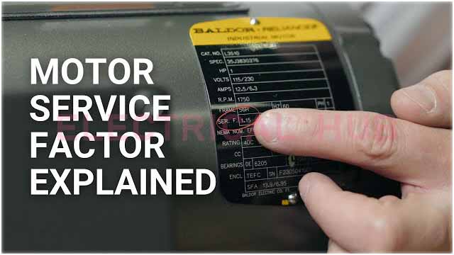
Motor Service Factor and Overloading Detection: Best Overview
Introduction to Motor Service Factor
The Motor Service Factor (SF) is a crucial parameter in the design and operation of electric motors. It represents the capacity of a motor to operate above its rated horsepower (HP) without overheating or suffering damage. A motor with a service factor of 1.15, for instance, can operate at 115% of its rated capacity under specific conditions.

Table of Contents
Definition and Calculation of Service Factor
The Service Factor is typically specified on the motor’s nameplate and is defined as:
Service Factor (SF)= Maximum Safe Operating Power/Rated Power of the Motor
For example, a motor with a rated power of 100 HP and a service factor of 1.15 can safely operate at:
Maximum Power=100×1.15=115 HP
This means the motor can handle an additional 15% load above its rated capacity without sustaining damage.
Significance of Motor Service Factor
The service factor provides a safety margin, allowing for short-term overloads or variations in operating conditions without risking the motor’s longevity or efficiency. It helps accommodate situations such as:
Voltage fluctuations: Variations in supply voltage can affect motor performance, and the service factor provides a cushion.
Load variations: Temporary increases in load can be managed without immediately risking motor failure.
Environmental conditions: Motors may operate in environments with higher temperatures or lower cooling efficiency. The Motor service factor compensates for these harsher conditions.
Technical Insights into Service Factor
The service factor is not just a static number but reflects the motor’s ability to handle additional stress. For instance:
Temperature Rise: The primary concern with operating above the rated HP is the increased temperature. A higher service factor indicates that the motor is designed to dissipate heat more effectively.
Insulation Class: Motors with higher service factors generally have better insulation, which can withstand higher temperatures without degrading.
Efficiency: Operating a motor above its rated capacity can lead to efficiency losses. However, motors with a higher service factor are typically designed to minimize these losses.
Motor Overloading: Causes and Consequences
Motor overloading occurs when the motor operates beyond its rated capacity for an extended period. This can happen due to several reasons:
Mechanical binding: Increased load due to friction or other mechanical issues.
Electrical issues: Voltage imbalance or phase loss can lead to unequal loading on the motor windings.
Incorrect sizing: Using a motor that is too small for the application can result in overloading.
Know more about how to select overload relay for motor
The consequences of motor overloading include:
Excessive heat generation: This can lead to insulation failure and eventually motor burnout.
Reduced efficiency: Overloading typically results in higher energy consumption for the same output.
Mechanical damage: Prolonged overloading can cause wear and tear on the motor components, leading to premature failure.
Methods for Detecting Motor Overloading
Current Measurement
The most direct method of detecting motor overloading is by measuring the current drawn by the motor. If the current exceeds the motor’s rated current, the motor is likely overloaded.
Formula:
Overload Percentage=((Measured Current−Rated Current)/Rated Current)× 100%
This will indicate the overload percentage while below formula is for current overload ratio.
Current Overload Ratio (COR) = Measured Current (I)/ Rated Current (Irated)
If the COR is greater than 1, the motor is drawing more current than it is rated for, indicating overloading.
Temperature Measurement
Overloading leads to excessive heating. Measuring the motor’s temperature can provide insights into its loading condition.
Temperature Rise:
Temperature Rise= Temperature of Motor (Tmotor)−Ambient Temperature (Tambient)
If the temperature rise is higher than the motor’s rated temperature rise, overloading is likely.
Power Measurement
Motor overloading can also be detected by measuring the power consumed by the motor. Power (P) is given by:
Three-phase Power Formula:
P=1.372×V×I×cos(ϕ)
Where:
- V = Line Voltage
- I = Line Current
- cos(ϕ) = Power Factor
If the measured power exceeds the motor’s rated power, overloading is present.
Vibration Analysis
Overloading can also cause abnormal vibrations in the motor, which can be detected using vibration sensors. A motor operating under load conditions beyond its design capacity will typically show increased vibration levels.
Infrared Thermography
This method uses infrared cameras to detect hotspots on the motor surface, indicating areas of excessive heating due to overloading.
Practical Considerations
When dealing with motor overloading, it’s essential to consider:
Operating Environment: Motors in hot, dusty, or humid environments might overheat faster and require more frequent monitoring.
Maintenance: Regular maintenance can prevent conditions that lead to overloading, such as bearing wear or misalignment.
Load Matching: Ensure the motor is correctly sized for the load. An oversized motor can lead to inefficiencies, while an undersized motor will likely overload.
Conclusion
Understanding and monitoring the motor service factor and potential overloading conditions are critical for ensuring motor longevity, efficiency, and safety. By employing methods like current measurement, temperature monitoring, and vibration analysis, overloading can be detected early, preventing costly downtime and repairs. Properly managed, the service factor becomes a vital tool in optimizing motor performance and extending its service life.
Sources:
- National Electrical Manufacturers Association (NEMA) Standards
- IEEE Standards for Motor Protection and Testing
- “Electric Machinery Fundamentals” by Stephen J. Chapman
- Industry-specific guidelines from motor manufacturers like Siemens and ABB
Worth Read Posts
- Power Transformer Testing
- Power Transformer Parts
- Hysteresis Loss and Eddy Current Loss
- Derivation of Hysteresis Losses
- Transformers: Important Types, Features & Components
- Transformer Tests Before Commissioning
- Transformer Electrical Interview
Follow us on LinkedIn, “Electrical Insights,” to get the latest updates on electrical engineering. For the latest jobs follow us on “Jobs Corner“.


