L293D Motor Driver Datasheet And Pin Configuration
Table of Contents
L293D Motor Driver Datasheet contains the information about features of the motor driver module. The L293D is a popular motor driver IC that is widely used in robotics and electronics projects. It is a dual H-bridge driver, which means it can drive two DC motors or one stepper motor.
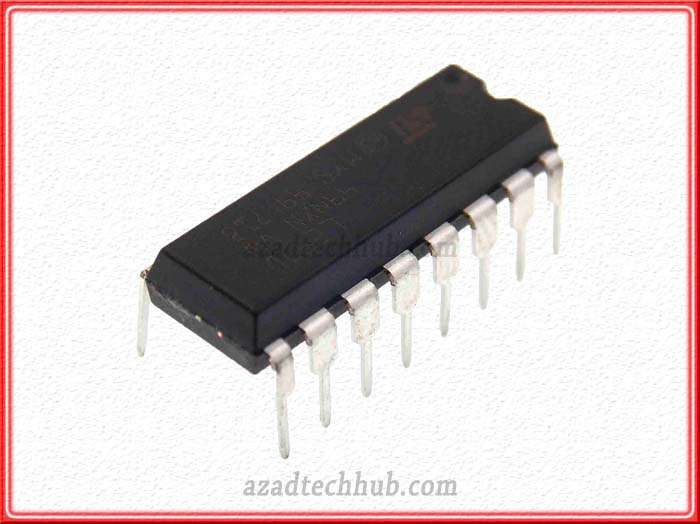
The L293D motor driver datasheet provides detailed information about the operating characteristics of the device, including its electrical specifications, pin configuration, and recommended usage. In this article we will explore l293d motor driver IC datasheet in detail.
Electrical Detail of l293d motor driver ic
The l293d motor driver module datasheet provides detailed information about the electrical specifications of the device. This includes l293d motor driver input voltage, the maximum voltage and current ratings. Further it contains the output voltage and current ratings, and the thermal resistance of the IC. The L293D can operate with a maximum voltage of 36 volts, and it can provide up to 600mA of current per channel. The IC has a low voltage drop, which means it can provide high efficiency even when operating at high currents.
Pin Configuration
The L293D motor driver datasheet also provides information about the pin configuration of the device. The l293d motor driver – Arduino IC has 16 pins, which are divided into two sections: the control section and the power section. The control section consists of pins 1-4 and 15-16, while the power section consists of pins 5-14. Pins 1 and 9 are used to control the direction of the motor, while pins 2 and 10 are used to enable or disable the motor. Pins 3 and 11 are used to control the speed of the motor, while pins 4 and 16 are used to provide power to the IC.
how to use l293d motor driver
The L293D motor driver datasheet also provides recommendations for the usage of the device. For example, it is recommended to use decoupling capacitors on the power supply pins to reduce noise and stabilize the voltage. It is also recommended to use heat sinks to dissipate heat generated by the IC, especially when operating at high currents. The datasheet also provides information about the recommended operating conditions, such as the maximum ambient temperature and the minimum input voltage.
The L293D motor driver datasheet provides valuable information for engineers and hobbyists who are designing circuits that require motor control. By carefully reading and following the recommendations in the datasheet, designers can ensure that their circuits operate reliably and efficiently. The L293D is a versatile and reliable motor driver IC that can be used in a wide range of applications, and its datasheet is an essential resource for anyone who wants to use this device in their projects.
Additional Information in L293D Motor Driver Datasheet
In addition to the basic information about the L293D motor driver۔ L293D motor driver datasheet also provides additional information that can be useful in designing circuits. For example, the datasheet provides detailed timing diagrams that show the relationships between the input signals and the output signals of the device. These timing diagrams can be helpful in understanding the behavior of the L293D and designing circuits that meet specific requirements.
The L293D motor driver datasheet also provides information about the internal structure of the L293D. This includes details about the input and output circuits, as well as the power supply and ground connections. By understanding the internal structure of the device, designers can make informed decisions about how to use the L293D in their circuits.
Another useful feature of the L293D motor driver datasheet is its application notes. These application notes provide practical examples of how to use the L293D in various types of circuits, including DC motor control, stepper motor control, and bidirectional motor control. The application notes include circuit diagrams, sample code, and performance data, which can be helpful in designing and testing circuits.
The L293D motor driver datasheet includes information about the environmental and safety considerations for the device. This includes details about the maximum operating temperature, the ESD sensitivity of the device, and the recommended handling and storage procedures. By following these recommendations, designers can ensure that their circuits are safe and reliable, even in harsh environments.
The L293D motor driver datasheet is a comprehensive resource for anyone who is designing circuits that require motor control. The datasheet provides detailed information about the electrical specifications, pin configuration, recommended usage, internal structure, application examples, and environmental and safety considerations for the device. By carefully reading and following the recommendations in the datasheet, designers can ensure that their circuits are efficient, reliable, and safe. The L293D motor driver is a versatile and widely used device, and its datasheet is an essential tool for anyone who wants to use this device in their projects.
Using the L293D Motor Driver
The L293D motor driver is widely used in robotics, industrial automation, and consumer electronics applications. It is often used in conjunction with microcontrollers or other control systems to provide precise control over the speed and direction of DC motors or stepper motors. The L293D can also be used to control solenoids, relays, or other high-current loads.
When using the L293D motor driver, it is important to follow the recommendations in the datasheet. This includes providing decoupling capacitors on the power supply pins, using heat sinks to dissipate heat, and avoiding ground loops or other sources of noise. It is also important to ensure that the motor or load is within the rated voltage and current specifications of the L293D.
To control a DC motor with the L293D, the motor is typically connected to pins 3 and 6 or 11 and 14, depending on the desired direction of rotation. The enable pins (2 and 10) are used to turn the motor on or off, and the PWM input (pin 3 or 11) can be used to vary the speed of the motor. The direction control pins (1 and 9) are used to select the direction of rotation of the motor.
To control a stepper motor with the L293D, the motor is typically connected to pins 3-6 or 11-14. The enable pins (2 and 10) are used to enable or disable the motor, and the step and direction inputs are typically connected to pins 1 and 9, respectively. The L293D can also be used to drive a unipolar stepper motor, in which case an additional diode network is required.
Conclusion
The L293D motor driver is a versatile and widely used device that provides precise control over the speed and direction of DC motors or stepper motors. Its datasheet provides comprehensive information about the electrical specifications, pin configuration, recommended usage, internal structure, application examples, and environmental and safety considerations for the device. By following the recommendations in the datasheet, designers can ensure that their circuits are efficient, reliable, and safe. The L293D motor driver is an essential tool for anyone who wants to control motors or other high-current loads in their projects.
Some Related Questions
What is the specification of L293D motor driver?
The L293D is a dual H-bridge motor driver IC that is designed to provide bidirectional control of DC motors and stepper motors. The specifications of the L293D motor driver include:
- Supply voltage range: 4.5 V to 36 V
- Maximum output current: 600 mA per channel (1.2 A peak)
- Continuous output current: 0.6 A per channel
- Maximum output voltage: 1.2 V (with Vcc = 4.5 V)
- Low quiescent current: 0.6 mA per channel (typical)
- Thermal shutdown protection
- Overcurrent protection
- Internal clamp diodes for inductive load transient suppression
- Input logic voltage range: TTL or CMOS compatible
- Operating temperature range: -40°C to +150°C
The L293D motor driver also has a 16-pin DIP (dual in-line package) or SOIC (small-outline integrated circuit) package, which makes it easy to use in various types of circuits. The pin configuration of the L293D includes two H-bridges with four input pins, two output pins, and two enable pins for each H-bridge. The pins are labeled and grouped together to simplify the wiring and reduce the chance of errors during circuit assembly.
What are the parts of the L293D motor driver?
The L293D motor driver is a multi-functional integrated circuit that consists of several parts, including:
H-bridges: The L293D has two H-bridges, each of which is composed of four power transistors. The H-bridges allow the L293D to control the direction of the motor by reversing the polarity of the voltage applied to it. Each H-bridge can handle a maximum current of 600 mA, with a peak current of 1.2 A.
Input pins: The L293D has four input pins (1, 2, 7, and 10), two for each H-bridge. These pins control the direction and speed of the motor. Pins 1 and 2 are used to set the direction of the motor, while pins 7 and 10 are used to enable or disable the H-bridge.
Output pins: The L293D has four output pins (3, 6, 11, and 14), two for each H-bridge. These pins are connected to the motor and provide the voltage and current required to drive it. The output pins are labeled as follows: 3 and 6 are the output pins for H-bridge 1, while 11 and 14 are the output pins for H-bridge 2.
Enable pins: The L293D has two enable pins (2 and 10), one for each H-bridge. These pins are used to turn on or off the H-bridge. When the enable pin is set to high, the H-bridge is turned on, and the motor can be controlled. When the enable pin is set to low, the H-bridge is turned off, and the motor stops.
Protection diodes: The L293D has built-in protection diodes that prevent damage to the device and the motor due to back EMF (electromotive force) generated by the motor. These diodes provide a path for the current to flow when the motor is turned off, preventing damage to the device and other components in the circuit.
Voltage regulator: The L293D also has an internal voltage regulator that regulates the voltage supplied to the device, making it possible to use the L293D with a wide range of power supplies.
Overall, the L293D motor driver is a highly integrated device that combines several components into a single package, making it a convenient and reliable solution for controlling DC motors and stepper motors in a wide range of applications.
Follow us on LinkedIn”Electrical Insights” to get the latest updates in Electrical Engineering. You can also Follow us LinkedIn to see our latest posts.
Recent Posts:
- Best Electrical Engineering Schools in Maryland – Top Accredited Universities & Program Comparison GuideDiscover the best electrical engineering schools in Maryland with this complete guide covering top accredited universities, program strengths, admission insights, and career-focused academic options for future engineers.
- Best Electrical Engineering Schools in Minnesota – Top Accredited Colleges & Degree Programs GuideDiscover the best electrical engineering schools in Minnesota with this complete guide covering accredited universities, program strengths, career prospects, and admission insights to help you choose the right engineering degree path.
- Best Electrical Engineering Schools in Oregon – Top Accredited Universities & Program GuideDiscover the best electrical engineering schools in Oregon with this comprehensive guide covering accredited universities, program strengths, career prospects, and admission insights to help you choose the right engineering degree path.
- Best Electrical Engineering Schools in Ohio | Top Accredited Universities & Program GuideDiscover the best electrical engineering schools in Ohio with this comprehensive guide covering accredited universities, program strengths, admission insights, and career-focused education options to help you choose the right path in electrical engineering.
- Best Electrical Engineering Schools in Mississippi | Top Accredited Universities & Program GuideDiscover the best electrical engineering schools in Mississippi with this complete guide covering accredited universities, program strengths, admission insights, and career-focused engineering education options for future engineers.
- How to Calculate Earth Cable Size | Complete Electrical Grounding Calculation GuideLearn how to calculate earth cable size with practical formulas, standards-based methods, and step-by-step guidance for safe electrical grounding design. This guide explains conductor sizing, fault current considerations, and compliance tips to help engineers and technicians select the correct earthing cable efficiently.
- Best Electrical Engineering Schools in Georgia | Top Accredited Universities & Degree ProgramsDiscover the best electrical engineering schools in Georgia with accredited programs, modern research facilities, and strong career outcomes. Compare top universities, admission insights, and program strengths to choose the right path for your engineering future.
- Best Transformer Testing Companies in Canada | Trusted Electrical Testing Experts & Utility Service ProvidersDiscover the best transformer testing companies in Canada offering reliable diagnostic services, power system analysis, and substation support. Compare top-rated providers to ensure safety, performance, and compliance for your electrical assets.

