Floating Gate MOSFET: A Comprehensive Guide
floating gate mosfet
A floating gate MOSFET (Metal-Oxide-Semiconductor Field-Effect Transistor) is a specialized type of MOSFET used primarily in non-volatile memory devices like EEPROMs (Electrically Erasable Programmable Read-Only Memories) and flash memory.
It’s a fundamental component in these types of memory devices because it can store a charge on its floating gate, which can be used to represent binary data (0s and 1s) even when the power is turned off.

Table of Contents
what is a floating gate?
A floating gate is a crucial component found in certain types of transistors, particularly in non-volatile memory devices like EEPROMs (Electrically Erasable Programmable Read-Only Memories) and flash memory.
It’s a specialized element within the transistor structure that can trap and store electrical charge, and this charge storage mechanism is used to represent data in these memory devices.
Floating gates are essential in non-volatile memory technologies like EEPROMs and flash memory, as they enable the long-term storage of data by manipulating the trapped charge. These memory devices are widely used in various electronic devices for data storage, including USB drives, SSDs, memory cards, and more.
floating gate mosfet working
The operation of a floating gate MOSFET, often used in non-volatile memory devices like EEPROMs and flash memory, is crucial to understanding its functionality. Here’s a more detailed explanation of how a floating gate MOSFET works:
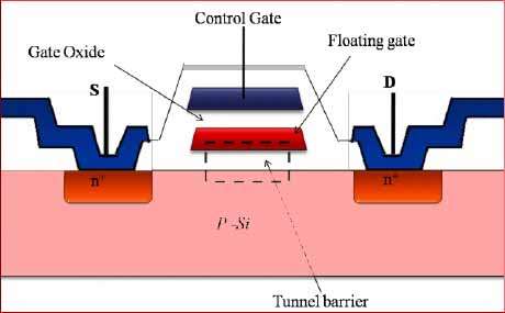
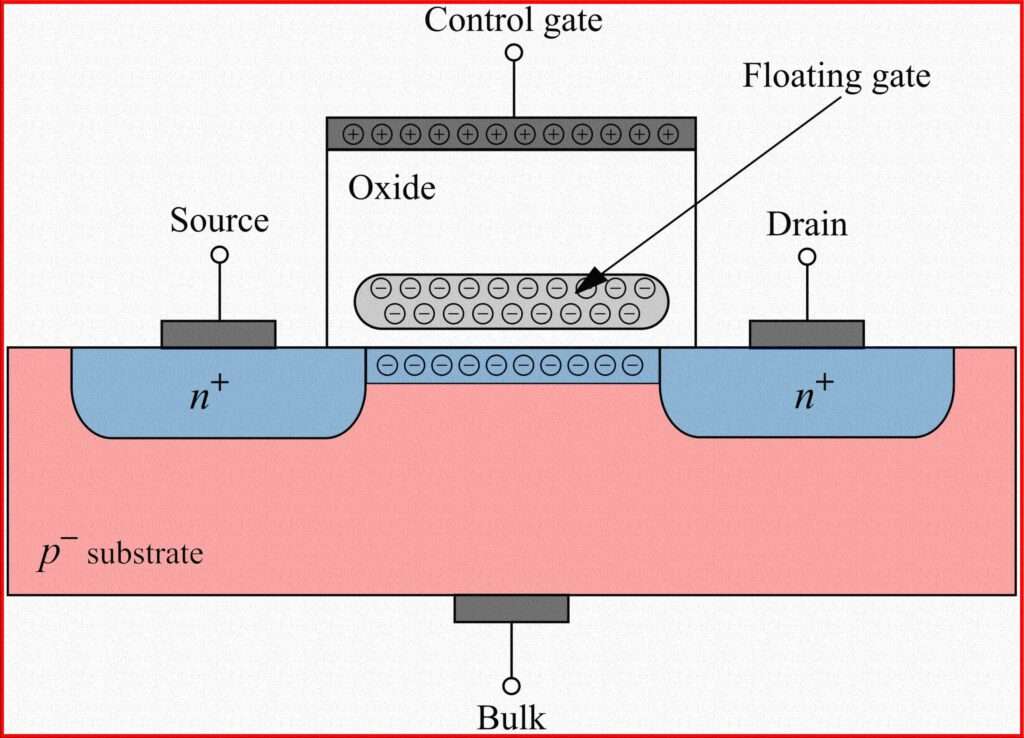
Basic MOSFET Structure: Like a standard MOSFET, it consists of three main terminals: source, drain, and gate. It also has an additional element called the “floating gate,” which is surrounded by insulating materials, typically silicon dioxide.
Floating Gate and Control Gate: The floating gate is electrically isolated from the other terminals by insulating layers (typically silicon dioxide). It is located between the control gate and the channel.
The control gate is connected to the control circuitry and is used to apply voltages to the floating gate.
Programming (Writing): To program or write data to the floating gate, a high voltage (typically 10-15V) is applied to the control gate.
This high voltage generates an electric field through the insulating layers, allowing electrons to tunnel through the insulator and onto the floating gate.
Electrons tunnel onto the floating gate, creating a negative charge on it. This negatively charged floating gate affects the operation of the MOSFET.
Erasing: To erase data or reset the floating gate to its original state, a different high voltage with an opposite polarity is applied to the control gate.
This high voltage causes the trapped electrons on the floating gate to tunnel back through the insulator, effectively removing the charge.
Read Operation: During a read operation, a moderate voltage is applied to the control gate. The presence or absence of charge on the floating gate affects the threshold voltage of the transistor.
If the floating gate has a significant charge (representing a logic ‘1’), it increases the threshold voltage, allowing current to flow between the source and the drain when a voltage is applied to the source.
If the floating gate has no charge (representing a logic ‘0’), the threshold voltage remains unchanged, and the transistor remains off.
Data Retention: The charge on the floating gate is typically trapped for a long time, allowing data to be retained for extended periods, even when power is disconnected.
Endurance and Data Integrity: Floating gate MOSFETs have a limited number of write/erase cycles before they may degrade. Careful control of programming and erasing voltages is required to maintain data integrity.
The key to the operation of a floating gate MOSFET is the ability to trap or remove charge on the floating gate, which alters the transistor’s behavior and is used to store binary data. This ability to store data without power and withstand multiple write/erase cycles makes it a crucial component in non-volatile memory devices.
floating gate mosfet block diagram
A Floating Gate MOSFET (Metal-Oxide-Semiconductor Field-Effect Transistor) is a type of transistor commonly used in non-volatile memory devices like Flash memory. It is a key component in NAND and NOR Flash memory cells. A block diagram of a Floating Gate MOSFET typically consists of the following components:
Control Gate (CG): This is the terminal used to control the transistor. Applying a voltage to the control gate determines whether the transistor is in an ON or OFF state.
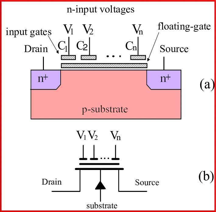
Floating Gate (FG): This is a conductive gate that is electrically isolated or “floating” within the device. The charge on the floating gate determines the threshold voltage and, therefore, the state of the transistor.
Source (S) and Drain (D): These are the terminals where current flows through the transistor. The source is where electrons enter, and the drain is where they exit when the transistor is in the ON state.
Substrate/Body: Depending on the type of MOSFET (N-channel or P-channel), this terminal may be connected to the source or left unconnected (as in the case of most NAND Flash memory).
Tunneling Oxide Layer (TOX): This is a thin insulating layer that separates the floating gate from the rest of the device. It allows for the tunneling of electrons during programming and erasing operations.
Control Gate Oxide Layer (CGOX): This is another insulating layer that separates the control gate from the floating gate.
Poly-Silicon Layer: The floating gate and control gate are typically made of poly-silicon, a material with good conductivity properties.
Channel Region: The region between the source and drain terminals where current flows when the transistor is in the ON state.
Floating Gate Charge: The charge on the floating gate (electron or hole) is used to modify the transistor’s threshold voltage, which determines whether it is ON or OFF. Adding or removing the charge from the floating gate is how data is stored and erased in Flash memory devices.

In operation, when a voltage is applied to the control gate, it creates an electric field that allows electrons to tunnel through the tunneling oxide layer onto or off of the floating gate. This changes the threshold voltage of the transistor and switches it between the ON and OFF states, which is how data is stored and read in Flash memory cells.
floating gate mosfet amplifier
A floating gate MOSFET amplifier, often referred to as a “Floating-Gate Amplifier” or “Charge-Coupled Amplifier (CCA),” is a specialized type of amplifier circuit that uses floating gate MOSFET transistors to amplify and transfer charges rather than voltage or current.
These amplifiers are typically used in certain niche applications, particularly in charge-coupled devices (CCDs) and image sensors.
Here’s a basic overview of how a floating gate MOSFET amplifier works:
Floating Gate MOSFET Transistors: Instead of standard voltage-controlled MOSFETs, floating gate MOSFET amplifiers use MOSFETs with a floating gate, which can store electric charge. These MOSFETs can be programmed to store a specific amount of charge on their floating gates.
Input Stage: The input signal is converted into an electric charge, which is then stored on the floating gate of the input MOSFET. The amount of charge stored is proportional to the input signal.
Amplification: The stored charge on the input MOSFET’s floating gate affects its threshold voltage and, consequently, the current flowing through the transistor. This change in current is used to amplify the input signal.
Transfer of Charge: The amplified charge is transferred to the floating gate of the next MOSFET in the amplifier chain.
Output Stage: The charge is further amplified and processed by subsequent stages of floating gate MOSFETs until it reaches the output of the amplifier.
Readout: The final output can be read by detecting the charge on the last floating gate, typically by measuring the current it generates when a voltage is applied.

Floating gate MOSFET amplifiers are used in applications where high precision, low noise, and high dynamic range are required. They are commonly used in image sensors, such as CCDs, where they can efficiently capture and amplify charges generated by photons, resulting in high-quality images.
floating gate mosfet applications
Floating gate MOSFETs find various applications primarily in non-volatile memory devices and specialized analog circuits due to their unique ability to trap and store electrical charge. Here are some common applications of floating gate MOSFETs:
Non-Volatile Memory Devices:
EEPROM (Electrically Erasable Programmable Read-Only Memory): Floating gate MOSFETs are a crucial component in EEPROMs. They store data by trapping and releasing electrons on the floating gate. EEPROMs are used in various applications, such as storing firmware and configuration data in microcontrollers and other embedded systems.
Flash Memory: NAND and NOR flash memory utilize floating gate MOSFETs to store data. These memory types are widely used in USB drives, solid-state drives (SSDs), memory cards, and other data storage devices.
Charge-Coupled Devices (CCDs):
Floating gate MOSFETs are used in CCDs, which are image sensors used in digital cameras, camcorders, and scientific instruments. They capture and transfer charge packets generated by incoming photons, allowing for the conversion of light into electronic signals with high precision and low noise.
Analog Signal Processing:
Sample-and-Hold Circuits: Floating gate MOSFETs can be used in sample-and-hold circuits to store and buffer analog voltages for further processing in analog-to-digital converters (ADCs).
Charge Amplifiers: In specialized applications where low noise and high sensitivity are essential, charge amplifiers based on floating gate MOSFETs can be used. These amplifiers amplify the charge stored on the floating gate, rather than voltage or current.
Radiation Dosimetry:
Floating gate MOSFETs are used in radiation dosimetry to measure ionizing radiation levels. The radiation-induced charge is trapped on the floating gate, allowing for precise measurement and monitoring of radiation exposure in medical and industrial applications.
Programmable Analog Devices:
Floating gate MOSFETs can be used in programmable analog devices, such as programmable analog filters and voltage references, where fine-tuning and calibration are required.
Sensors and Detectors:
Floating gate MOSFETs can be integrated into sensors and detectors for various applications, such as chemical sensing, temperature sensing, and pressure sensing.
Calibration and Trimming:
In some analog circuits, floating gate MOSFETs are used for calibration and trimming purposes. By adjusting the charge on the floating gate, the performance of the analog circuit can be fine-tuned.
Scientific Instruments:
In research and scientific instruments, floating gate MOSFETs can be used in precision measurements and data acquisition systems where stability and low noise are critical.
These are just some of the applications where floating gate MOSFETs play a crucial role. Their ability to trap and store charge reliably over time makes them valuable in scenarios where non-volatile data storage or precise charge handling is required.
Follow us on LinkedIn”Electrical Insights” to get the latest updates in Electrical Engineering. You can also Follow us on LinkedIn and Facebook to see our latest posts on Electrical Engineering Topics.
Worth Read Posts


