How HRC Fuses Operate? Important Types & Selection Tables
HRC Fuses or high rupturing capacity fuses are one of the types of fuses. Whenever there is a current flow in any circuit, it generates a specific amount of heat. This heat dissipation is because of the resistance of that specific circuit. on the other hand, every circuit inside a network has some limit to the flow of current. Devices or components connected to that circuit has also their current and voltage ratings.
Read More About
Crossing these limits may damage the equipment. Once the limit of current exceeds in the single phase or three phase circuit, a fault may occur in the circuit which we usually refer to as the short circuit. Upon short circuit, the fault can be a single phase to ground if the network circuit is single phase or it can be three phases in the case of a three-phase network. In case of fault, a very large number of current flows in the circuit. to avoid damage to the equipment and the circuit, we employ a “Fuse” in the circuit.
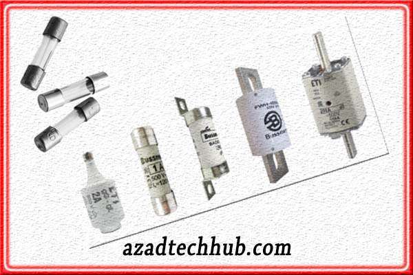
As the secondary wiring on the distribution side is rated at low amperes so it can melt easily with heavy amperes and heat. So, fuses play an important role in the circuits. There are a variety of fuses available in the market, but here in this specific article, we will be discussing the operation and applications of HRC fuses in detail.
What is HRC Fuse?
HRC or high rupturing capacity fuse is a type of fuse that can carry a high amount of current for a specific time period without blowing or melting. If during the rated amount of time, the fault removes, the HRC fuse will not blow. The enclosure of HRC fuses is made of chemical material or sometimes glass in smaller fuses.
On both ends of the HRC fuse, a metallic cap is fitted. These metallic caps weld with the fusible wire inside. In smaller fuses, we see there is a glass material enclosure while in larger fuses we see there is some chemical compound enclosure. Smaller fuses are air-tightened so that environmental factors do not contribute to the blowing of the fusing wire. Let’s discuss fuse law before continuing to HRC fuse as this law is the basis of every fuse blowing.
What is Fuse Law?
Fuse state that the current through the conductor is directly proportional to the conductor diameter raised to a power of 1.5. generally written as
I = Kd^1.5
What this equation means is the fusing current will increase as the diameter of the wire increases while it will only be possible if the conductor remains the same. As every conductor has a different value of K. copper has the highest value of around 80 and then aluminum follows copper at 59. The values for “K” have been shown in below for different metals.
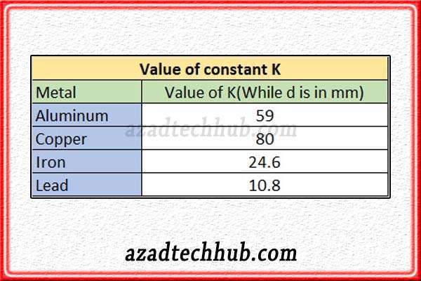
In the case of copper and aluminum, as the constant “K” is higher so these conductors are preferred in fuses due to in time fusing of the wire. There is another contributor to the fusing of fuses which is the specific resistance of the metal. As this factor decides the fusing time or the time to attain the melting point. In the below table, we have mentioned the melting points as well as the specific resistance of metals.
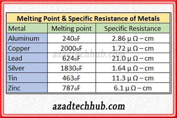
Now we know about the fusing law and factors which contribute to the fusing of the conductor inside the enclosure. Let’s discuss the construction of HRC fuses.
Construction of HRC Fuse
The outer enclosure of the HRC fuse is of some sort of ceramic material but in small fuses, it seems to be of glass. Fuses with high current carrying capacity contain some sort of powdered material inside along with the fusing wire.
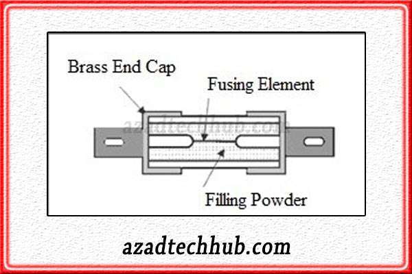
On both ends, we see end caps in smaller fuses while according to application, HRC fuses design changes. The fusing wire in HRC fuses is mostly copper or silver as both metals have a specific resistance of very low value as compared to other metals.
Operation of HRC Fuse
As in normal conditions and normal loading currents fuse element allows the current to pass and doesn’t heat up on normal currents. While as the current limit reaches due to some fault in the circuit, the fusing element starts to melt. The melting fumes react with the filled powder inside the HRC fuse. The purpose of this powder is basically to limit the reaction during the fusing of the fusing wire inside. Hence the filled powdered material helps in quenching the arc generated during the HRC fuse blow.
HRC fuses have inverse-time characteristics, which means as the current gets higher, the fuse blowing time reduces. As the current gets lower, the fusing time gets high. This tends to make HRC fuses safe in critical circuits where the short circuit currents are high. As HRC fuse will blow in smaller time in higher currents.
If in any circuit of HRC fuse, overloading of the circuit occurs then the fuse will not blow, unless this overloading condition remains for an extended period. This extended time for each HRC fuse varies with the type and rating of the fuse. Mostly in solar systems we see HRC fuses along with Lithium ion batteries on the DC side side. Lithium ion batteries current and power is large, therefore HRC fuses remain a good choice to install as a backup protection of circuit breaker.
Types of HRC Fuses
There are mainly three types of HRC Fuses available in the market which include NH Type fuses, DIN-type fuses, and then comes blade-type fuses. We will discuss each type of fuse separately to have a comprehensive understanding and their application in circuits correctly.
NH TYPE HRC Fuse
NH HRC fuses are used in case of overloads and in short circuits in the low voltage or the medium voltage side. These are the one-time-use fuses as they blow, they can’t be repaired. These fuses are employed in starting motors or different types of pumps for short ratings.
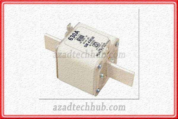
These NH fuses provide protection against overloads of about 2Amps to around 1250Amps. These fuses have high performance and reliability in critical circuits like small pumps and motors as discussed above. These fuses can be employed in circuits against overloads and short circuits to avoid damage to circuit components.
DIN TYPE HRC Fuse
These fuses find applications on a broader level against short circuits. We can find DIN fuses in transformer protections as the fault-clearing time of DIN fuses is high. That’s why these fuses are reliable in short circuits and overcurrent.
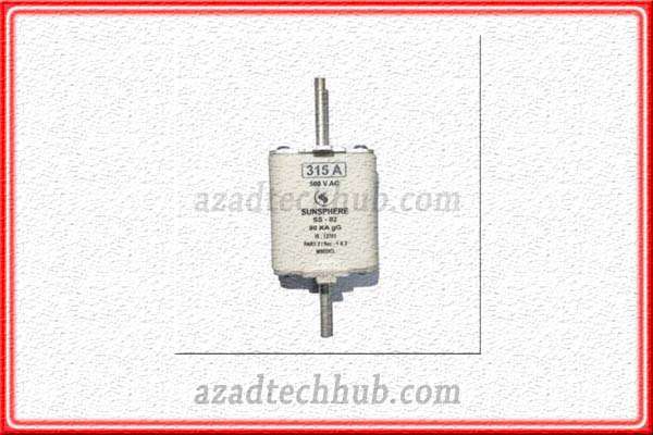
The rated short circuit capacities are over 120KA. DIN fuse links can provide protection to motors against overloads where these uses are used along with DOL starters inside motor control gears. These DIN fuses are available for motors rating around 450KW. Where these fuses have a short circuit rating of around 80KA.
BLADE TYPE HRC Fuse
Blade-type HRC fuses are also referred to as spade-type fuses or Plug-in fuses. These fuses we normally see in the automotive and domestic circuits. These fuses are also called automotive fuses. The outer enclosure is made up of plastic material and the two metallic terminals are encapsulated in the body.

These fuses have a very light body and a current rating of around 1 to 40Amps. Due to its small size, these fuses are very lightweight. Main applications include vehicles, domestic circuits, and backup protection for motors or pumps. Blade-type HRC fuse gives protection against overload and the short circuit in the circuit.
Characteristics of HRC Fuse
The HRC fuse has inverse-time characteristics which means as the current increases, the fuse blowing time decreases. As the current decreases, the fuse blow time will increase which means the circuit will function in the same manner as before.
As discussed above the fusing time depends upon the value of constant “K”, the specific resistance of the fusing wire, the melting point of metal, and the amount of current flowing through the circuit. These all factors contribute to the blowing of the HRC fuse.
How to Select HRC Fuses
There are various factors that must be considered before selecting the HRC fuses.
- System voltages must be the same as of the circuit where need to install.
- Application of installation is important like either to protect cables or the motors.
- If in motors or pumps HRC fuse is installed, the inrush current of the motor must be considered.
- In solar system HRC fuses must be selected according to the strings current.
- The curve of the fuse including time-current and cut-off curve.
- The amount of current and short circuit current.
- Full load currents of motors or pumps.
Selection Table for LOW Voltage HRC Fuses
Selecting the appropriate HRC (High Rupturing Capacity) fuses requires considering various parameters to ensure optimal protection for electrical systems. Here’s a detailed selection table for HRC fuses based on their rated parameters. Keep in mind that this is a general guideline, and specific requirements may vary based on regional standards, regulations, and applications.
| Rated Current (Amperes) | Rated Voltage (Volts) | Breaking Capacity (kA) | Tripping Characteristics | Typical Applications |
| 6A | 230V, 400V | 25kA, 36kA | gG (General Purpose) | Small-scale machinery, industrial equipment |
| 10A | 230V, 400V | 25kA, 36kA | gG, aM (Motor Protection) | Motors, pumps, fans |
| 16A | 230V, 400V | 25kA, 36kA | gG, aM | Industrial applications, power distribution panels |
| 20A | 230V, 400V | 25kA, 36kA | gG, aM | Medium-sized machinery, control circuits |
| 32A | 230V, 400V | 25kA, 36kA | gG, aM | Heavy machinery, industrial processes |
| 50A | 230V, 400V | 36kA | gG, aM | High-power industrial equipment |
| 63A | 230V, 400V | 36kA | gG, aM | Large motors, substations, high-power distribution |
| 100A | 230V, 400V | 50kA | gG, aM | Critical industrial systems, heavy-duty applications |
| 125A | 230V, 400V | 50kA | gG, aM | High-power machinery, power-intensive applications |
This detailed selection table for HRC fuses takes into account various parameters including rated current, rated voltage, breaking capacity, and tripping characteristics. However, other factors such as specific application requirements, short-circuit currents, and coordination with other protective devices should also be considered for accurate selection.
Selection Table for HIGH Voltage HRC Fuses
here’s a table outlining the selection of High Voltage HRC (High Rupturing Capacity) fuses based on their rated parameters. Please note that this table is a general guideline, and specific requirements may vary based on regional standards, regulations, and applications. Always consult relevant guidelines and professionals for accurate selection.
| Rated Current (Amperes) | Rated Voltage (kV) | Breaking Capacity (kA) | Tripping Characteristics | Typical Applications |
| 6A | 3.3kV, 6.6kV, 11kV | 40kA, 50kA | aM | Distribution transformers, substations |
| 10A | 3.3kV, 6.6kV, 11kV | 40kA, 50kA | aM | Medium-voltage switchgear, power distribution systems |
| 16A | 3.3kV, 6.6kV, 11kV | 40kA, 50kA | aM | Industrial plants, power generation systems |
| 20A | 3.3kV, 6.6kV, 11kV | 40kA, 50kA | aM | High-voltage equipment, utility substations |
| 32A | 3.3kV, 6.6kV, 11kV | 40kA, 50kA | aM | High-power industrial applications |
| 50A | 3.3kV, 6.6kV, 11kV | 50kA | aM | Critical power systems, energy-intensive industries |
| 63A | 3.3kV, 6.6kV, 11kV | 50kA | aM | High-current equipment, heavy-duty machinery |
| 100A | 3.3kV, 6.6kV, 11kV | 63kA | aM | Major substations, power distribution networks |
| 125A | 3.3kV, 6.6kV, 11kV | 63kA | aM | Large-scale industrial complexes, power infrastructure |
This table provides a general guideline for selecting High Voltage HRC fuses based on their rated parameters. It’s important to consider specific application requirements, system coordination, and other factors for accurate fuse selection.
Advantages of using HRC Fuse
The main advantages of HRC fuses include the following but are not limited to these.
These fuses have low electromagnetic stress and hence have inverse-time characteristics.
HRC Fuses have higher breaking capacity and high-speed operation.
Good choice on the DC side of the solar system.
As these are enclosed so there is no emission in case of blowing.
HRC fuses have longer life and durability.
These fuses remain unaffected by environmental conditions.
Due to different types, these fuses can be employed in different applications according to need.
Rated capacities can extend to 1250Amps and being a cheap solution can be used as a reciprocal to the circuit breaker.
Drawbacks of using HRC Fuses
Some drawbacks of HRC fuses exist and are listed below as every component has some drawbacks.
After each operation HRC fuses need to be replaced so incur some extra cost in operation although less but this factor exists.
As fuses of different ratings can fit in the same fuse holder so there can be some Mis operation or error in maintenance.
Some fuse body types are open so there would be a danger of safety to some types of HRC fuses which are open.
The HRC fuses which are openly installed, during operation create heat that may affect the surrounding components of circuits.
Always recommended to be installed with a fuse base which obviously increases the overall cost of installation.
Applications of HRC Fuses
Applications of HRC fuses have been listed below but are not limited to these.
- In ring networks where loads are critical.
- Circuit breakers backup protection.
- As short circuit protection of circuit components.
- In high voltage switchgear.
- Inside motors stator windings to protect the winding.
- On DOL starters motor or pumps control gears.
- In transformers to protect the circuits on secondary.
- In automotive electrical circuits due to compact sizes.
- In the solar system we find these HRC fuses on the DC side for opening and closing of the DC side.
This was all about HRC fuses where we discussed their types, characteristics, operation, advantages, disadvantages, and applications in detail. In conclusion, we can say that selection of the HRC fuses should be according to the application but keeping in view the system-rated capacities and current ratings. Here’s a question for you, which type HRC Fuse is more reliable in auto sector and why?
Follow us on LinkedIn”Electrical Insights” to get the latest updates in Electrical Engineering. You can also Follow us LinkedIn and Facebook to see our latest posts on Electrical Engineering Topics.

