Active reactive and Apparent power: How to draw the Power triangle?
Table of Contents
Introduction
Active reactive and apparent power are fundamental concepts in electrical engineering. Active power, also known as real power or true power, represents the actual power consumed or generated by a device or system. It is measured in watts and is responsible for performing useful work.
Unlike active power, reactive power does not perform any work but is essential for maintaining the magnetic fields in inductive components such as motors and transformers. Reactive power is measured in volt-amperes reactive (VAR).
Apparent power, on the other hand, is the combination of both active and reactive power and is measured in volt-amperes (VA). It represents the total power flowing in a circuit and is crucial for sizing equipment and determining the capacity of electrical systems.

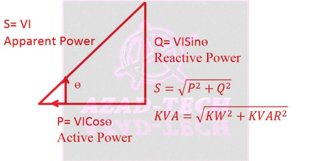
Understanding the relationship between active, reactive, and apparent power is crucial for efficient power management. In an AC circuit, the apparent power is the vector sum of active power and reactive power. It can be visualized using a power triangle, where the active power is the horizontal component, the reactive power is the vertical component, and the hypotenuse represents the apparent power.
The power factor, which is the cosine of the phase angle between active power and apparent power, indicates the efficiency of power utilization in a system. A high power factor implies efficient power consumption, whereas a low power factor indicates reactive power consumption, leading to increased energy losses.
Balancing active reactive and apparent power is important for optimizing power systems. Power factor correction techniques are employed to reduce reactive power and improve the overall power factor of a system. This involves the use of power factor correction capacitors or inductors to offset the reactive power and bring the power factor closer to unity.
By improving power factor, energy losses are minimized, voltage stability is enhanced, and the capacity of the electrical system can be better utilized. Effective power management strategies take into account active reactive and apparent power to ensure efficient and reliable operation of electrical systems in various applications, ranging from industrial plants to residential buildings.
Active Reactive and Apparent Power
We can calculate active reactive and apparent power with the help of different relationships. These three power types, we can only find in 3 phase power system. Understanding the difference and basics of 3 phase power system is necessary before moving forward with the power relationships.
Active reactive and Apparent power are fundamental concepts in electrical engineering. Active power represents the actual power consumed or produced by a device or system. It is the real power that is converted into useful work, such as mechanical energy or light. Active power is measured in watts and is denoted by the symbol P. Understanding active power is crucial for efficient energy management and optimizing power generation and consumption.
Reactive power, on the other hand, is the power that oscillates between the source and the load without being converted into useful work. It arises due to inductive or capacitive elements in the electrical system. Reactive power is measured in volt-amperes reactive (VAR) and is denoted by the symbol Q.
It is essential to manage reactive power to maintain voltage stability and reduce power losses in the transmission and distribution networks. Active reactive and Apparent power play a significant role in power factor correction and ensuring the efficient operation of electrical systems in industries, commercial buildings, and residential areas.
Active power
The power that the load consumes is an active power in actuality. Loads like induction motors, pumps, and auxiliary equipment actually dissipate the active power available to the circuits. Alternative names for Active Power include “Actual Power,” “True Power,” and “Useful Power. We can also call it “Real Power” and we denote it with “P” which is measured in units of Watts “W”.
If we have one volt of voltage and one ampere of current then we call it one watt.
One watt= W = 1V x 1A
The above scenario is valid for DC circuits and in DC circuits there is no difference phase angle of voltage and current. Therefore, voltages and current are in phase producing an angle of zero degrees. Due to which cosɵ, becomes zero. So, the power factor in DC circuits is always one or unity. Calculate the power factor using our online power factor calculator and improve using the power factor improvement calculator. How about frequency in DC circuits?
The frequency in DC circuits is zero, as there is no sinusoidal wave of voltage or current. There is no zero crossing in DC circuits and voltage and currents have a straight-line waveform.
However, the situation is more complicated in AC circuits due to the phase difference of some angle “ɵ” between current and voltage. Due to the sinusoidal waveform of both voltage and current, AC circuits always have a frequency or zero crossings. As a result, the load actually receives the average value of power (Active Power) given by the below formula.
P = V x I x Cosɵ
V = voltage
I = current
Cosɵ = Power Factor
Read our article regarding the Power factor and its improvement.
Apparent Power
If we simply multiply the voltages and current in ac circuit, then we can call it apparent power. Apparent power is denoted by “S”.
S = V x I
Apparent power is the total amount of power in any AC Power circuit that has been consumed or dissipated. It is basically the combined value of the active and the reactive of any circuit. The above formula tells us that we can derive units of apparent power in volt-amperes (VA). This is why generators and transformers are always rated in KVA rating as this is the resultant or combination of the other two forms of power.
We normally calculate circuits in apparent powers where we calculate the apparent powers of all the circuits. Demand factor and diversity factors are then used to estimate the actual circuits loading. Learn more about demand factor and diversity factor here.
Apparent power can be represented as the below formulas.
S = V I
In Power Terms,
S = √ (P2 + Q2)
S = √ (Active power2 + Reactive Power2)
In Ratings, we can say,
KVA Rating = √ (kW2 + KVAR2)
Reactive power
Reactive power is the energy that continually oscillates between the source and the load and we can represent it by the letter “Q”.
This power refers to the power that is initially held and then released as an electrostatic field or a magnetic field, depending on whether the load is an inductor or a capacitor. Reactive power plays an important role in power factor value. If reactive is inductive in nature we get the power factor leading and in the case of capacitive loads we get the power factor lagging. Reactive power can be represented as the below formula.
Q = V x I x Sin
V= Voltage
I = Current
We can measure reactive power in terms of “VAR” where one VAR is equivalent to one-volt x one ampere. We can calculate Reactive power from the below formulas.
Reactive Power = √ (Apparent Power square– Active power square)
In terms of rating,
KVAR = √ (KVA2 – kW2)
Also, read about 3 phase power and single phase power beforehand for better understanding the power factor in 3 phase power.
Active reactive and apparent power in the power triangle
From the above detail, now we can draw the active power, reactive power, and apparent power of any circuit in the form of a power triangle as below.

Reactive power for RLC series circuit
From the above discussion and formulas, we can say that the apparent is the result of active and reactive power in any circuit. Mainly, the reactive component is an assumption in electrical circuits. Inductors and capacitors behave differently when we talk about reactive power.
In inductors, current leads the voltages across the inductor by 90 degrees. In other words, we can say voltage lags behind current by 90 degrees. As AC voltage and current are sinusoidal in the waveform, the inductor stores energy in the first quarter cycle of the current as the current increases. Then it releases the same amount of energy stored back to the supply source. The cycle continues in a negative half cycle also.
Energy Stored in Inductor
We can represent energy stored by the inductor by the below formula.
E = ½ LI2
When we look at the capacitive loads, they behave differently. They generate reactive power by storing energy by the voltages. As the voltage in capacitors leads the current by 90 degrees, therefore they store energy in a similar way as inductors do.
Energy Stored in Capacitor
We can represent Capacitors’ energy storage by the below formula.
E= ½CV2
So, overall, we can conclude that in RLC series circuits, inductive loads consume the reactive component and capacitive loads generate it. But what happens to the active power? Does it remain the same? The answer to this is “YES”. As the reactive component is theoretical or imaginary, therefore it doesn’t consume or generate the active power in any circuit.
Reactive power and Power Factor “PF”
The power factor (PF) measures how a consumer efficiently uses electrical power. It is the ratio of active/real power measured in watts “W” and apparent power (S) measured in volt-amperes “VA”. As soon as the ratio reaches unity, the circuit will be close to the resistive circuit and then active consumption will be equal to apparent consumption. In other words, the reactive component will be zero.
But this doesn’t happen in actual circuits where we have motors as inductive loads and capacitors as capacitive loads. Due to inductive loads the power factor drops and hence we face a penalty on our electricity bills.
Power Factor Penalties
Installing power factor correction capacitors is one method of avoiding the reactive power penalty or charges. Due to power factor dropping issues, manufacturers incorporate capacitors into most domestic appliances. Therefore, utility companies only charge residential customers for the active power consumed in kilowatt-hours (KWH). They usually don’t face this penalty of poor power factor.
On the other hand, industrial consumers who use a 3-phase supply have vastly lower power factor “PF” due to running inductive loads including motors and machines. Therefore, the electricity utility companies take these industrial consumers’ power factor into notice and charge them a penalty if their power factor “PF” drops below a recommended value.
The reason behind charging is that utility companies have to bear the losses incurred by the poor power factor consumers. They require larger conductors, larger transformers, larger switchgear, etc. to handle the losses or we can say larger loads.
Read more regarding the power factor here.
Also, read about 3 phase power and single-phase power to have a clear understanding of active, reactive, and apparent power and their role in power factor.
Worth Read Posts
Follow us on LinkedIn”Electrical Insights” to get the latest updates in Electrical Engineering. You can also Follow us on LinkedIn and Facebook to see our latest posts on Electrical Engineering Topics.


