Solar Panel for Home: Important Tips to Know
Table of Contents
Introduction
Whenever we install solar panel for home, the solar systems always connect to some load to supply the current requirement. With the changing Load, how do solar panels react? The answer to this question is pretty long and requires a detailed study of solar system design. We have covered complete solar system design in a video series which you can watch and follow by clicking here.
We already demonstrated in our previous article the working of solar panels and their different parameters. So, let’s have a look how does a typical solar panel look like:

The voltages across positive and negative terminals are open circuit voltages. This is a single solar panel diagram, now let’s discuss the overall solar system diagram.
Block Diagram of a Solar Systems
Solar systems have two main parts in the block diagram. The first one is the direct current side which is generally solar panel for home. We can also call the solar panel side the DC side or the PV area of the project. Let’s have a look at the below figure,

In the above figure, we can see the applied power to the solar inverter is un-regulated DC Power but when it passes through the inverter circuit, it gets converted into regulated DC Power.
The power from the solar panels is fluctuating and does not have a constant value that’s why we call it unregulated DC power. Our appliances do not run on fluctuating voltages of direct current. The loads mostly run on alternating current “AC” with constant or stable voltages. Therefore we require inverters to first regulate the voltages and then convert them into alternating current or AC Power.
DC Side (Solar Panel for Home) of a Solar System
On the DC side of the solar systems, we have solar panels, a solar mounting structure, DC side fuses, breakers, isolators, and cables. We fasten the solar panels on the mounting structure. The mounting structure normally consists of mounting material which may include different types of channels and angle iron. These channels are made of aluminum and hot dip galvanized material. The solar panels’ unregulated dc power, goes through the “DC side” of the inverter.
In the “DC” compartment, we have a DC-to-DC converter circuit that converts the DC Voltages to a specific Value. The circuit also limits the output voltages to a value where those voltages can easily be converted to an equal AC signal. In our previous articles, we have discussed in detail the function of DC-to-DC converter circuits.
There are various kinds of DC converter circuits to step-down (Buck converter) and step-up converters(Boost converters). We have also shared the circuit diagrams for the above-mentioned circuits. You can read the article by clicking here.
Further, on the DC side of the inverter HRC fuses normally we in the circuits. HRC fuses refer to high rupturing capacity fuses which giver protection against overcurrent and short circuits. There are various types of HRC fuses, among them we can select according to our application. Read more about HRC fuses.
Low Pass and High Pass Filters in Solar Panel for Home
In solar system design, we need a stable output of 50Hz or 60Hz which can smoothly run our loads. After passing through the converter circuits, the signal passes through the filter circuits on the input side. We have also discussed RC low-pass and high-pass filter circuits in our previous articles. These filter circuits remove the unwanted spikes from the signals.
Inverters normally have filter circuits on both sides, the input, and the output side. These filter circuits also protect the inverter circuit from transient voltages or surges which may damage the circuit in case of any fault.
A low-pass filter circuit allows passing the signals having low frequencies and a high pass acts inversely to a low-pass filter circuit. Therefore, after the filter circuit, we get a smooth signal of the same frequency range. We can change the frequency ranges by just changing the circuit components’ values. The formulas have also been stated in the previous article, which you can read here.
How Does Load Respond To Solar System?
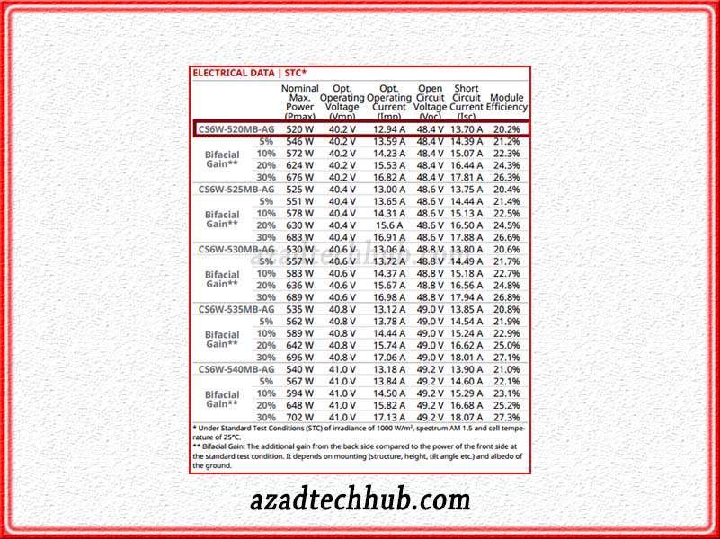
We always connect the solar system to a load. Before moving towards design, we must understand the basics of solar panel reaction when we connect it directly to the load. Therefore let’s look at the below module datasheet where we have chosen a module with a wattage of 520W.

Now when we take the voltages and current of this specific solar panel, we calculate the resistance by the ohms law equal to 3.106 ohms. So this is actually the load value that we can connect to this module. But as we know, the load never remains the same.
Let’s suppose the load has been decreased to 2 ohms, now what will be current by using ohm’s law? It will be around 20.1 Amperes. How much current our solar panel can supply? when we look at the datasheet, our solar panel can only provide 12.94 Amperes. So, what will happen now? As the load does not behave ideally means not remain constant, the solar panel will also not operate ideally.
What does it mean when we say the solar system will not behave ideally? It means solar panels will not operate on maximum power point to deliver the full power to the load. So, we are clear regarding a few factors which are important during the selection of a solar panel for home. For a better understanding, go through the IV Curve and power curve of solar panels which we have explained here.
There comes the role of the maximum power point tracker and its operation with a solar system. We will discuss the maximum power point tracker in our upcoming article.
Follow us on LinkedIn”Electrical Insights” to get the latest updates in Electrical Engineering. You can also Follow us LinkedIn to see our latest posts.
