IEC Standard-Based Earthing System Design for Commercial Buildings
In today’s electrical engineering landscape, Earthing System Design for Commercial Buildings is not just about safety—it’s a necessity governed by international standards. The IEC (International Electrotechnical Commission) standards provide the framework to ensure systems are safe, reliable, and efficient. Whether it’s a multi-story office complex or a shopping mall, designing the correct earthing system ensures the protection of both human lives and electronic assets.
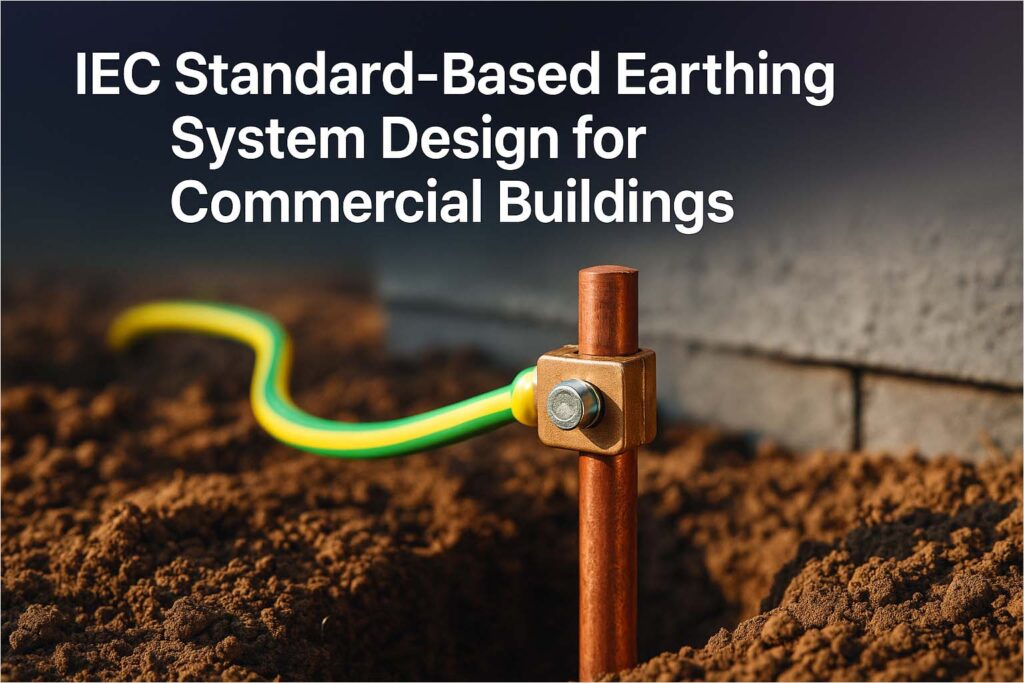
When done right, the earthing system mitigates electrical faults, ensures stable voltage levels, and provides a safe path for fault currents. This article covers everything you need to know about IEC Standard-Based Earthing System Design for Commercial Buildings, with practical insight into design parameters, compliance strategies, and essential components.
Why Earthing System Design for Commercial Buildings Matters
Proper earthing is critical for commercial infrastructure. With increasing electrical loads and complex installations, risks such as electric shocks, fire hazards, and equipment failure become more likely. A robust earthing system ensures:
- Protection from electrical faults
- Prevention of voltage surges
- Enhanced operational reliability
- Compliance with legal and regulatory requirements
Moreover, modern buildings use automation and sensitive equipment that require consistent and clean grounding. Poor design can lead to data loss, equipment damage, and expensive downtime.
Overview of IEC Standards Relevant to Earthing
The IEC standards offer comprehensive guidance for electrical safety and grounding systems. The key ones include:
| IEC Standard | Title | Relevance |
|---|---|---|
| IEC 60364 | Low-voltage electrical installations | Core standard for earthing and bonding |
| IEC 61000 | Electromagnetic compatibility (EMC) | Covers grounding for EMC performance |
| IEC 62305 | Protection against lightning | Focuses on earthing related to lightning safety |
| IEC 61557 | Electrical safety in distribution systems | Guidance on earth resistance measurement |
These standards serve as the backbone of Earthing System Design for Commercial Buildings and must be carefully followed by designers and consultants.
Types of Earthing Systems in Commercial Installations
Commercial buildings usually adopt one of the following earthing arrangements, as defined by IEC 60364:
TN System (Terra Neutral)
- Neutral is earthed at the source
- Exposed conductive parts are connected to that earth
- Common types: TN-S, TN-C, TN-C-S
TT System
- The supply has an earth, and the installation has a separate local earth
- Higher earth fault loop impedance
- Often used where the utility does not provide a reliable earth
IT System
- Supply system is isolated or has high impedance to earth
- Suitable for critical applications like hospitals
Each system has unique applications. For example, TN-S systems are often favored in commercial buildings due to their reliable performance and safety.
Steps in Earthing System Design for Commercial Buildings
Designing a compliant and effective earthing system involves a sequence of technical steps. Each stage must adhere to IEC standards for maximum safety and performance.
Know more about nec article 220
Step 1: Soil Resistivity Measurement
Soil resistivity significantly affects the design. High resistivity requires deeper or multiple electrodes. Use the Wenner four-pin method or Schlumberger method to measure.
| Soil Type | Typical Resistivity (Ohm-m) |
|---|---|
| Clay | 10 – 50 |
| Loam | 50 – 100 |
| Sand | 100 – 200 |
| Gravel | 200 – 1000 |
| Rock | >1000 |
Step 2: Electrode Type and Configuration
Electrode selection depends on resistivity, available area, and design constraints. Common choices include:
- Rod electrodes (Copper-bonded or GI)
- Strip or tape electrodes
- Plate electrodes (GI or copper)
- Earth mats and meshes for high fault levels
Multiple rods connected in parallel reduce resistance more effectively than a single deep rod.
Step 3: Sizing of Earthing Conductors
Conductor sizing depends on fault current, duration, and thermal withstand capacity. IEC 60364 suggests the following formula for cross-sectional area:
S = √(I² × t) / k
Where:
S = cross-sectional area (mm²)
I = Fault current (A)
t = fault duration (s)
k = material constant (dependent on conductor type)
Use copper for durability and high conductivity, especially in critical environments.
Step 4: Earthing Resistance Limits
According to IEC 60364, acceptable earth resistance values are:
| System Type | Maximum Earth Resistance (Ohms) |
|---|---|
| TN System | < 1 Ω |
| TT System | ≤ 10 Ω |
| IT System | Not fixed, but must ensure fault detection |
A resistance below 1 Ohm is ideal for large commercial buildings with heavy machinery and sensitive electronics.
Step 5: Lightning Protection and Equipotential Bonding
Incorporate lightning protection as per IEC 62305. Equipotential bonding connects all metallic non-current-carrying parts to the earth system to prevent dangerous voltage differences.
Focus on:
- Bonding water, gas pipes, structural steel
- Using surge protection devices (SPDs)
- Integrating the LPS (Lightning Protection System) with the main earth grid
Step 6: Periodic Testing and Maintenance
Testing should follow IEC 61557, including:
- Earth resistance testing (Fall-of-potential method)
- Continuity testing of bonding conductors
- Visual inspection of corrosion or physical damage
Document each test to ensure traceability and compliance.
Common Challenges in Earthing System Design for Commercial Buildings
While the guidelines are clear, several practical issues often arise:
- High soil resistivity: Solved by using chemical electrodes or deep driving rods.
- Space constraints: Use of vertical electrodes or earth enhancement compounds like bentonite or conductive cement.
- Corrosion: Prefer copper or use corrosion-resistant coatings for steel components.
- Complex bonding: Multi-service buildings (IT, HVAC, BMS) require integrated bonding strategies to avoid loops.
Addressing these challenges during the design phase improves the system’s long-term reliability.
Integration with Other Electrical Systems
Earthing System Design for Commercial Buildings must not be standalone. It should integrate with:
- Building Management Systems (BMS)
- Fire detection and suppression systems
- Renewable energy systems like solar panels
- Data centers and IT infrastructure
Make sure all systems share a common grounding reference to prevent circulating currents and voltage surges.
Regulatory and Safety Compliance
Adherence to IEC standards is not just best practice—it’s often a legal requirement. National adaptations like BS 7671 (UK), IS 3043 (India), or NEC (USA) reference IEC guidelines heavily.
Authorities require:
- Earthing design documentation
- Soil resistivity reports
- Test records
- Manufacturer data sheets for conductors and electrodes
Keep all compliance paperwork ready for audits and certifications.
Best Practices for Long-Term Reliability
Here are a few golden rules:
- Never rely on water pipes or rebar as the sole earth electrode
- Always use test links to isolate and measure earth resistance
- Install earth pits with inspection chambers
- Ensure proper labeling of earthing conductors
- Avoid sharp bends and tight loops in earthing conductors
These practices enhance both safety and maintainability.
To better understand the Fault Current at Transformer Secondary and how it impacts earth conductor sizing, read our detailed guide on transformer fault analysis. Similarly, integrating the Differential Relay in Transformer system with proper grounding ensures better protection during high current faults.
Designing an IEC Standard-Based Earthing System for Commercial Buildings is a meticulous task. It demands technical know-how, field experience, and a strict adherence to global standards.
In summary, follow IEC 60364 for your earthing system design. Focus on soil resistivity, electrode configuration, proper sizing, and regular testing. When these fundamentals are in place, your commercial building will be grounded in safety and reliability.
Follow Us on Social:
Subscribe our Newsletter on Electrical Insights for latest updates from Electrical Engineering Hub
#EarthingSystemDesign, #IECEarthingStandards, #CommercialBuildingSafety, #ElectricalGrounding, #BuildingEarthingSystem, #ElectricalDesignStandards, #IEC60364, #GroundingSolutions, #ElectricalEngineering, #SafeBuildingDesign, #ElectricalSystemDesign, #GroundingDesign, #EarthingForBuildings, #IECStandards, #ElectricalSafety



I believe you have noted some very interesting points, regards for the post.