Star Delta Starter Diagram with Timer: A Comprehensive Guide
A star delta starter diagram with timer is essential for understanding the working of this motor starter configuration. It is widely used to start three-phase induction motors smoothly, reducing the starting current and mechanical stress. This article explores the star delta starter diagram, its control and power circuits, applications, advantages, disadvantages, and auto-switch connections.
Star Delta Starter Diagram With Timer
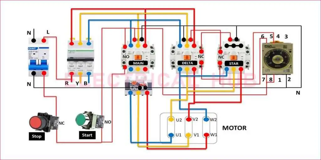
Table of Contents
Table of Contents
What is a Star Delta Starter?
A star delta starter is an electrical starting method used for three-phase induction motors to minimize the starting current. It initially connects the motor in a star configuration and then switches to a delta configuration after a set time. This transition is achieved using a timer in the control circuit.
Star Delta Starter Diagram with Timer
The star delta starter diagram with timer consists of two main circuits:
- Power Circuit – Connects the motor to the power supply and controls its operation in star and delta configurations.
- Control Circuit – Uses a timer and contactors to switch the motor from star to delta mode automatically.
Star Delta Starter Diagram Control Circuit
The control circuit of star delta starter ensures a smooth transition between star and delta configurations. The timer plays a vital role in this process by maintaining the motor in star mode for a preset duration before switching to delta mode.
Components of Star Delta Starter Control Circuit:
- Contactor K1 (Main Contactor) – Connects power to the motor.
- Contactor K2 (Star Contactor) – Initially connects the motor windings in star.
- Contactor K3 (Delta Contactor) – Switches the motor to delta configuration.
- Overload Relay – Protects the motor from overcurrent.
- Timer – Controls the time delay between star and delta switching.
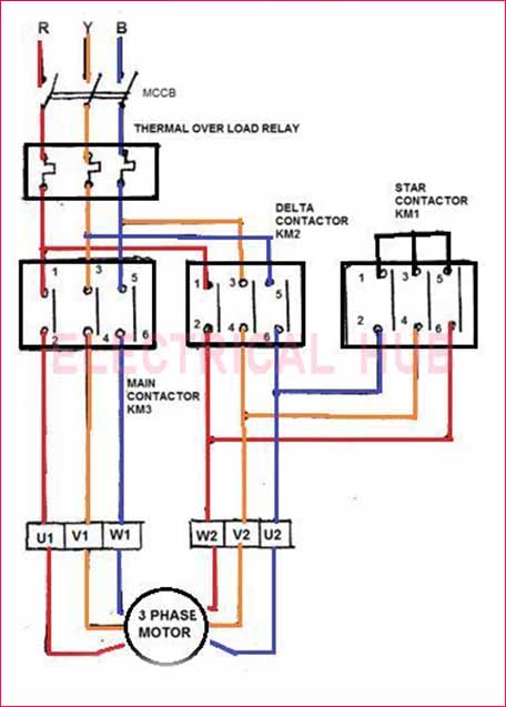
Star Delta Starter Diagram – 3 Phase Power Circuit
The power circuit consists of three-phase connections that determine how the motor operates in star and delta mode.
Power Circuit Working:
- Step 1: When the start button is pressed, the main contactor (K1) and star contactor (K2) are energized.
- Step 2: The motor runs in star connection, reducing the starting current.
- Step 3: After the set time, the timer deactivates the star contactor (K2) and activates the delta contactor (K3).
- Step 4: The motor switches to delta connection for normal operation.
Star Delta Starter Drawing
A star delta starter drawing illustrates how the power and control circuits are connected. The diagram includes three-phase power supply, contactors, overload relay, and a timer to manage the switching sequence.
Star Delta Starter Auto Switch Connection
A star delta starter with auto switch connection allows the motor to start and switch modes automatically. This reduces human intervention and enhances efficiency in industrial applications.
Star Delta Starter Definition and Difference
Definition:
A star delta starter is a motor starter that starts a three phase induction motor in star mode and later switches it to delta mode to reduce the initial current surge.
Difference Between Star and Delta Connection:
| Feature | Star Connection | Delta Connection |
|---|---|---|
| Configuration | Windings connected in star | Windings connected in delta |
| Voltage per phase | Lower (Line voltage / √3) | Full line voltage |
| Current Drawn | Lower starting current | Higher running current |
| Torque | Lower starting torque | Full-rated torque |
Star Delta Starter Advantages and Disadvantages
Advantages:
- Reduces starting current (approximately 1/3rd of direct-on-line starting).
- Minimizes voltage drop in the electrical system.
- Prevents mechanical stress on the motor.
- Simple and cost-effective solution for motor starting.
Disadvantages:
- Not suitable for heavy-load motors due to low initial torque.
- Complex wiring and more components compared to direct-on-line (DOL) starters.
- Time delay setting is crucial for smooth switching.
Star Delta Starter Application
A star delta starter is widely used in:
- Pumps – Reduces water hammering effects in large pumps.
- Compressors – Limits starting current in high-power applications.
- Fans and Blowers – Prevents excessive inrush current.
- Textile and Paper Mills – Ensures smooth motor operation.
Conclusion
The star delta starter diagram with timer is a crucial tool for understanding motor starting circuits. By using a control circuit with a timer, the starter ensures smooth transitions between star and delta modes, reducing electrical and mechanical stress. This method is widely used in industries due to its efficiency and cost-effectiveness.
For more details, check out these resources:
Follow Us on Social:
Subscribe our Newsletter on Electrical Insights for latest updates from Electrical Engineering Hub
StarDeltaStarter #ElectricalEngineering #MotorControl #Automation #ControlCircuit #PowerCircuit #IndustrialAutomation #MotorStarter #StarDeltaConnection #ElectricMotors #WiringDiagram #ElectricalDesign #EngineeringDiagrams #ElectricalSystems #ElectricalMaintenance

