What Are 555 Timers? Important Things to Know
The 555 timer is a versatile integrated circuit (IC) that has been a staple in electronic design since its introduction in 1971. This small but powerful chip has found its way into countless applications, from simple timing circuits to complex pulse generators. In this article, we’ll explore the ins and outs of 555 timers, their functionality, and their widespread use in electronic projects.
Table of Contents
What Are 555 Timers: Understanding the Basics
What are 555 timers? A 555 timer is a precision timing device that can produce accurate time delays or oscillations.
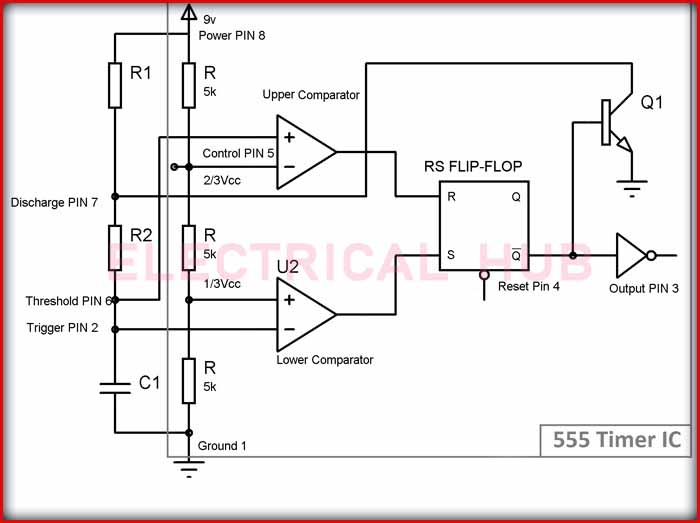
The name “555” comes from the three 5 kΩ resistors used in its internal voltage divider circuit. This integrated circuit is designed to be stable and reliable, making it an excellent choice for both hobbyists and professional engineers.
What Are 555 Timers Used For?
555 timers are incredibly versatile and can be found in a wide range of applications. Some common uses include:
- 1. Time delay generators
- 2. Pulse width modulators
- 3. Oscillators and clock generators
- 4. LED flashers
- 5. Tone generators
- 6. DC-DC voltage converters
The flexibility of the 555 timer allows it to be configured in various modes, making it suitable for both simple and complex circuit designs.
How Do 555 Timers Work?
To understand how 555 timers work, it’s essential to look at their internal structure and operating principles. The 555 timer consists of several key components:
- 1. Two voltage comparators
- 2. A flip-flop
- 3. A discharge transistor
- 4. Three 5 kΩ resistors forming a voltage divider
These components work together to create the timing functionality of the IC. The voltage comparators monitor the input voltage and compare it to reference voltages set by the internal voltage divider. The flip-flop acts as a switch, controlling the output state based on the comparator inputs. The discharge transistor is used to rapidly discharge the timing capacitor, which is an external component connected to the 555 timer.
How to Trigger a 555 Timer Circuit
Triggering a 555 timer circuit is a crucial aspect of its operation. The trigger pin (pin 2) is used to initiate the timing cycle. When the voltage on this pin falls below one-third of the supply voltage, it causes the flip-flop to change state, starting the timing sequence. This triggering mechanism allows the 555 timer to respond to external events or signals, making it useful in various applications where precise timing control is required.
555 Timer as an Oscillator
One of the most common applications of the 555 timer is as an oscillator. In this configuration, the 555 timer produces a continuous stream of pulses or a square wave output. The frequency of these oscillations can be easily adjusted by changing the values of external resistors and capacitors connected to the timer.

To set up a 555 timer as an oscillator, it is typically configured in astable mode. In this mode, the timer continuously charges and discharges a capacitor through two resistors. The values of these components determine the frequency and duty cycle of the output waveform. This ability to generate stable, adjustable frequency signals makes the 555 timer an excellent choice for applications such as LED flashers, simple musical tone generators, and PWM (Pulse Width Modulation) controllers.
555 Timer Explained: Astable Mode
In astable mode, the 555 timer operates without a stable state, continuously oscillating between high and low output. Here’s a step-by-step explanation of how it works:
- 1. The capacitor begins to charge through both resistors.
- 2. When the capacitor voltage reaches 2/3 of the supply voltage, the upper comparator triggers the flip-flop, causing the output to go low and activating the discharge transistor.
- 3. The capacitor then discharges through one of the resistors and the discharge transistor.
- 4. When the capacitor voltage falls to 1/3 of the supply voltage, the lower comparator triggers the flip-flop, causing the output to go high and turning off the discharge transistor.
- 5. The cycle then repeats, creating a continuous oscillation.
This process allows the 555 timer to generate a stable frequency output, which can be fine-tuned by adjusting the values of the external resistors and capacitor.
What Are 555 Timers: Monostable Mode
While the astable mode is useful for generating continuous oscillations, the 555 timer can also operate in monostable mode. In this configuration, the timer produces a single pulse of a specific duration in response to a trigger input. This mode is particularly useful for creating precise time delays or for generating single pulses in response to external events.
In monostable mode, the 555 timer circuit typically includes a single resistor and capacitor for timing control. When triggered, the output goes high for a duration determined by the RC time constant. After this period, the output returns to its stable low state until triggered again. This functionality makes the 555 timer in monostable mode ideal for applications such as debouncing switches, creating time delays in control systems, or generating single pulses for other circuit elements.
What Are 555 Timers: Bistable Mode
Although less commonly used, the 555 timer can also be configured in bistable mode. In this setup, the timer acts as a flip-flop, with two stable states. The output changes state in response to trigger inputs, making it useful for simple latching circuits or as a memory element in digital systems.
How to Design with 555 Timers
When designing circuits with 555 timers, several factors need to be considered:
- 1. Power supply: The 555 timer can operate with a wide range of supply voltages, typically from 4.5V to 16V. Ensure that your power supply is compatible with the specific 555 timer variant you’re using.
- 2. Timing components: Carefully select the resistors and capacitors that determine the timing characteristics. Higher quality components will result in more accurate and stable timing.
- 3. Decoupling: Always use a decoupling capacitor close to the 555 timer’s power supply pins to reduce noise and ensure stable operation.
- 4. Output considerations: The 555 timer can source or sink up to 200mA, but be mindful of power dissipation limits. For driving higher current loads, consider using a buffer or driver circuit.
- 5. Triggering: Ensure that your trigger signal meets the required voltage levels and duration for reliable operation.
By taking these factors into account, you can create robust and reliable circuits using 555 timers.
What Are 555 Timers: Modern Variants and Alternatives
While the original 555 timer remains popular, modern variants have been developed to address specific needs:
- 1. CMOS versions: These offer lower power consumption and higher input impedance, making them suitable for battery-powered applications.
- 2. Dual 555 timers: ICs like the 556 contain two 555 timers in a single package, useful for more complex timing applications.
- 3. Programmable timers: Some modern ICs offer similar functionality to 555 timers but with digital programming capabilities for more precise control.
- Despite these alternatives, the classic 555 timer remains a popular choice due to its simplicity, reliability, and widespread availability.
Conclusion: The Enduring Legacy of 555 Timers
In conclusion, 555 timers have earned their place as one of the most versatile and widely used integrated circuits in electronics. Their combination of simplicity, reliability, and flexibility makes them an excellent choice for a vast array of timing and oscillator applications. Whether you’re a hobbyist working on a simple LED flasher or an engineer designing a complex control system, understanding “what are 555 timers” and how to use them effectively is a valuable skill in the world of electronics.
As technology continues to advance, the 555 timer’s fundamental principles remain relevant, ensuring its continued use in both education and industry. By mastering the use of 555 timers, electronics enthusiasts and professionals alike can unlock a world of creative circuit design possibilities, limited only by their imagination.
Worth Read Posts
- 555 Timer IC Pins Configuration
- Power Transformer Testing
- Power Transformer Parts
- Hysteresis Loss and Eddy Current Loss
- Derivation of Hysteresis Losses
- Transformers: Important Types, Features & Components
- Transformer Tests Before Commissioning
- Transformer Electrical Interview
Follow us on LinkedIn, “Electrical Insights,” to get the latest updates on electrical Engineering.


