3 Phase Motor Overload Relay Setting – Accurate Protection for Your Motor
In industrial and commercial systems, three-phase motors are the heart of many operations. They power pumps, compressors, conveyors, and countless other machines. But with great power comes the risk of overheating and failure. That’s where overload relays come in. Setting a 3 phase motor overload relay properly is not just good practice—it’s essential for safety and performance.
Table of Contents
Table of Contents

An overload relay protects your motor from drawing excessive current over a sustained period. Unlike a short circuit, which trips instantaneously, an overload builds up heat gradually. If not addressed, this heat can severely damage the motor winding insulation and reduce its lifespan.
Understanding the correct setting of a 3 phase motor overload relay involves knowing the motor’s nameplate data, operational load, and environmental conditions. Setting it too low may cause nuisance tripping. Too high, and the motor might burn out before the relay trips. Let’s walk through every essential detail.
Key Takeaways:
- The overload relay setting must match the motor’s full-load current.
- A relay that’s improperly set will either trip too often or fail to protect the motor.
- Always consider ambient temperature, duty cycle, and application type before finalizing settings.
Why Correct 3 Phase Motor Overload Relay Setting Matters
When motors are forced to work harder than designed, they draw more current. This could happen due to a jammed conveyor, dirty filters, misalignment, or increased mechanical load. If the excess current persists, it generates heat. This heat degrades insulation, reduces motor life, and increases fire hazards.
Overload relays sense this excessive current and cut power before the motor is damaged. But they are only effective if the settings are precise. That’s why understanding 3 phase motor overload relay setting is critical for motor protection and plant safety.
Most overload relays are either thermal, electronic, or bimetallic. The basic principle remains the same: detect overload and break the circuit when necessary. In 3-phase motors, the relay is connected in each phase and monitors current imbalance as well.
Know more about Earth Ground Testing: Clamp Meter vs Fall-of-Potential Method
Understanding Motor Nameplate and FLA
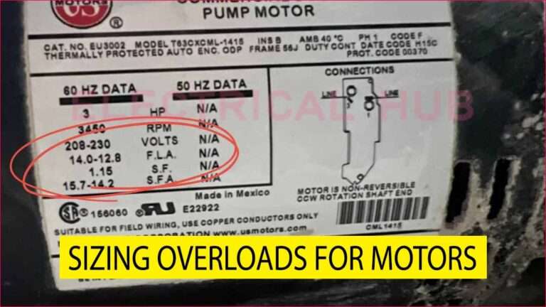
Before you set the overload relay, you must check the motor’s Full Load Amps (FLA). It’s mentioned on the motor nameplate. This is the current the motor will draw when operating under rated conditions.
Let’s say your motor nameplate mentions:
- Voltage: 400V
- Current: 22 Amps
- Power: 15 kW
- Power Factor: 0.85
Your overload relay setting should be very close to this 22 A value. But depending on the application and relay type, a percentage margin is applied.
Know more about motor overload setting table
Recommended Overload Relay Setting Range
Here’s a quick reference for overload relay setting for 3 phase motor based on standard practice:
| Motor Type | Relay Setting Range (% of FLA) | Notes |
|---|---|---|
| Standard Motor | 100% – 115% of FLA | Most common setting range |
| Severe Duty | 115% – 125% of FLA | For motors that can withstand high thermal rise |
| Frequent Start-Stop | 90% – 100% of FLA | To avoid overheating during frequent starts |
For example, if your motor has an FLA of 22 A:
- Set relay between 22 A and 25 A
- If the motor operates in harsh environments, set closer to 25 A
- For sensitive operations, set around 21 A to prevent overloading
Factors to Consider During 3 Phase Motor Overload Relay Setting
1. Ambient Temperature Compensation
Thermal overload relays are affected by the surrounding temperature. If your motor control panel is in a hot environment (above 40°C), the relay might trip early. Many modern relays have temperature compensation built-in. Always check the datasheet.
2. Duty Cycle of the Motor
Is the motor running continuously or intermittently? Continuous duty motors can tolerate higher thermal stress. For intermittent loads, consider lower overload settings to prevent overheating during starts.
Know more about Hybrid Solar Inverter Working Principle with Circuit Diagram
3. Application Type
Pumps and fans usually have steady loads. But crushers or mixers can spike suddenly. The overload relay setting should accommodate these load variations without frequent tripping.
4. Phase Imbalance or Single Phasing
Good overload relays detect current imbalance. A common issue in 3-phase systems is single phasing, where one phase fails. A quality relay will sense this and trip to protect the motor. Ensure your relay has this feature.
How to Set a 3 Phase Motor Overload Relay – Step-by-Step
- Read the motor’s nameplate and note the Full Load Amperes (FLA).
- Select a relay with a setting range that includes your motor’s FLA.
- Turn the dial or set the digital value on the relay to match 100% of the FLA.
- Apply 10–15% margin only if manufacturer or application conditions allow.
- Run the motor under load and check for nuisance tripping.
- Adjust slightly if needed, but never exceed 125% of FLA unless you’re fully aware of the thermal capacity and load profile.
- Monitor performance over a few days for stability.
Example: 3 Phase Motor Overload Relay Setting Calculation
Suppose we have a 10 HP motor with 400V supply and a Full Load Current of 14 A.
Step 1: Check relay range – Choose a relay that can be set between 12 A to 16 A.
Step 2: Set the dial to 14 A (100% of FLA).
Step 3: If the motor is driving a crusher with unpredictable loads, consider 10% higher:
Setting = 14 A + 10% = 15.4 A
Important: Never set beyond the motor service factor (usually 1.15 or 1.25). This means if FLA is 14 A and service factor is 1.15:
Max setting = 14 × 1.15 = 16.1 A
Know more about Grounding vs Bonding: Key Differences Explained
Modern Overload Relays vs Thermal Relays
Thermal Relays
- Cost-effective
- Slower response
- Affected by ambient temperature
- Easy to install
Electronic Relays
- More accurate
- Detect current imbalance and phase loss
- Adjustable time-delay settings
- Often communicate with PLCs or monitoring systems
For critical industrial processes, electronic overload relays offer better protection and diagnostics.
Know more about Transformer Cooling Methods: ONAN, ONAF, OFAF & More
Common Mistakes in Overload Relay Settings
- Setting the relay based on circuit breaker size, not motor FLA
- Ignoring the impact of frequent start-stop cycles
- Failing to verify actual current using clamp meters
- Using the same setting for all motors, regardless of application
Always treat each motor individually. The relay setting should reflect its actual job, load profile, and environmental condition.
Maintenance Tips for Overload Relays
- Monthly inspection for any tripping history
- Clean contacts and check for corrosion in bimetallic relays
- Test tripping function periodically to ensure relay response
- Monitor motor performance using thermal cameras or online tools
- Log every adjustment for tracking performance over time
Conclusion – Getting the 3 Phase Motor Overload Relay Setting Right
An overload relay may look like a small component, but it plays a massive role in protecting your expensive 3-phase motor. Whether you’re running HVAC units, irrigation pumps, or industrial machinery, the right 3 phase motor overload relay setting ensures safety, reliability, and long-term savings.
Know more about Star Delta Transformer Fault Current Distribution Explained
Always base your setting on the motor’s FLA, understand your application, and never guess. Measure, verify, and set with confidence. Overload protection is not a luxury—it’s a necessity.
Follow Us on Social:
Subscribe our Newsletter on Electrical Insights for latest updates from Electrical Engineering Hub
#3PhaseMotor, #MotorOverloadRelay, #RelaySetting, #MotorProtection, #ElectricalEngineering, #IndustrialAutomation, #MotorControl, #OverloadRelaySetting, #3PhaseProtection, #ElectricalSafety, #RelayCalibration, #ElectricMotorSafety, #PanelDesign, #MotorStarter, #MCCPanel

