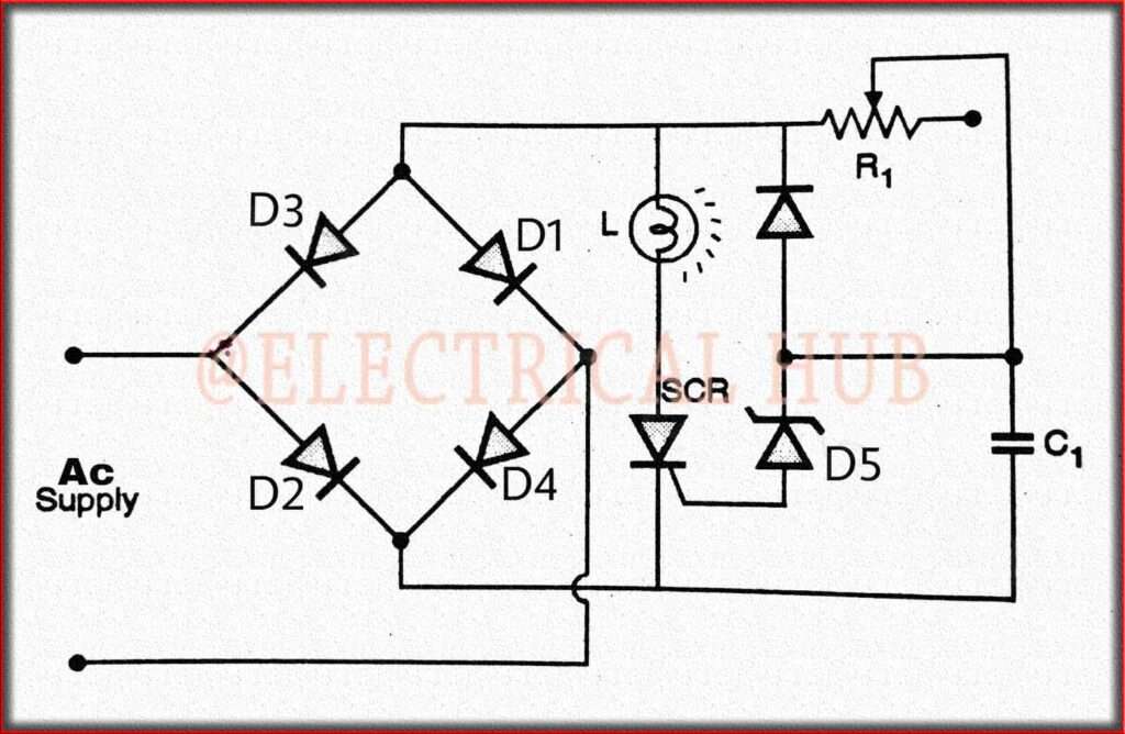
Thyristor Dimmer: A Quick Guide
A thyristor dimmer, also known as a silicon-controlled rectifier (SCR) dimmer, is an electronic device used to control the brightness or intensity of lighting or the speed of electric motors in various applications. It works by adjusting the voltage supplied to the load, such as an incandescent lamp or an AC motor, to control the output.

Components of a Thyristor Dimmer:
Thyristor (SCR): As mentioned earlier, the heart of a thyristor dimmer is the silicon-controlled rectifier (SCR). The SCR is a four-layer, three-junction semiconductor device that allows current to flow in one direction when triggered, and it remains conducting until the current flowing through it drops below a certain threshold. The two main terminals of the SCR are the anode and cathode, and it has a gate terminal used to control its firing.
Control Circuit: The control circuit is responsible for generating the trigger signal for the SCR. It typically includes components like a potentiometer or microcontroller, which allows users to set the desired level of dimming or motor speed. The control circuit generates a gate current that, when applied to the SCR’s gate terminal, triggers the SCR into conduction.
Snubber Circuit: Due to the abrupt switching action of the SCR, voltage and current transients can be generated, which may lead to electrical noise or stress on the components. A snubber circuit is often included to mitigate these transients. It typically consists of a resistor and a capacitor connected in parallel and connected in series with the load.
Working Principle of a Thyristor Dimmer
Initialization: When the power is initially applied or the dimmer is turned on, the SCR is in its non-conductive state. This means that no current flows from the anode to the cathode.
Triggering: As the user adjusts the control knob or input signal, the control circuit determines when to trigger the SCR. This timing is crucial because it determines when during the AC cycle the SCR will start conducting. The timing is often expressed as a phase angle (measured in degrees) or a delay time from the zero-crossing point of the AC waveform.
Conduction: Once the SCR is triggered, it enters a conductive state. It effectively shorts the load, allowing current to flow through it. Depending on the triggering point within the AC cycle, a portion of the AC waveform is passed to the load. The longer the SCR remains in the conductive state, the more power is delivered to the load.
Control and Dimming: By adjusting the triggering point within the AC cycle, the dimmer controls the amount of power delivered to the load. If the SCR is triggered closer to the zero-crossing point, it conducts for a shorter duration, resulting in lower power and dimmer output. Conversely, triggering the SCR later in the cycle increases power and brightness.
Zero-Crossing Detection: In some advanced thyristor dimmers, zero-crossing detection is employed. This means the SCR is triggered only when the AC voltage crosses zero volts, which helps reduce electrical noise and ensures smooth transitions during dimming.
how a thyristor dimmer typically works
Thyristor (SCR): The core component of the thyristor dimmer is the silicon-controlled rectifier (SCR), which is a type of semiconductor device. SCR allows current to flow in one direction only when triggered.
Control Signal: The thyristor dimmer receives a control signal to adjust the brightness or speed. This control signal is often generated by a user-operated knob or a microcontroller.
Phase Control: The most common method used in thyristor dimmers is phase control, where the thyristor is triggered at different points in each half-cycle of the AC waveform. This effectively chops off a portion of the AC voltage waveform, reducing the RMS voltage applied to the load.
Dimming Effect: By controlling the firing angle (the point in the AC cycle at which the SCR is triggered), the dimmer can vary the amount of power delivered to the load. When the SCR is triggered later in the AC cycle, less power is delivered, resulting in reduced brightness or speed. Conversely, triggering it earlier allows more power to pass, increasing the output.
Smooth Dimming: Thyristor dimmers can provide smooth and continuous dimming, making them suitable for applications where precise control of light or motor speed is required.
Applications of Thyristor Dimmer
Thyristor dimmers are commonly used in residential, commercial, and industrial settings for various purposes, including:
Residential Lighting: Dimming lights in homes to create different atmospheres and save energy.
Theater and Entertainment: Controlling stage lighting to set the mood and create effects.
Industrial Automation: Regulating the speed of electric motors in manufacturing processes.
HVAC Systems: Controlling the speed of fans and blowers in heating, ventilation, and air conditioning systems.
Commercial Lighting: Adjusting lighting levels in offices, retail spaces, and restaurants for ambiance and energy savings.
It’s vital to keep in mind that thyristor dimmers function well with resistive loads like incandescent bulbs but may not with all LED or fluorescent lighting due to their electronic drivers, which may require more complicated dimming procedures. Additionally, in sensitive applications, electromagnetic interference (EMI) caused by the usage of thyristor dimmers may need to be handled.
Follow us on LinkedIn”Electrical Insights” to get the latest updates in Electrical Engineering. You can also Follow us on LinkedIn and Facebook to see our latest posts on Electrical Engineering Topics.
Worth Read Posts


