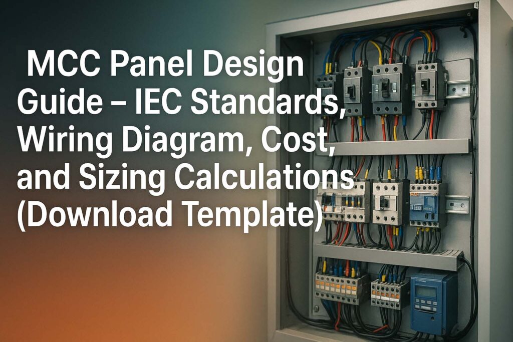
MCC Panel Design Guide PDF – IEC Standards, Wiring Diagram, Cost, and Sizing Calculations (Excel Template)
Motor Control Centers (MCC panels) form the backbone of modern industrial electrical systems. They are used in manufacturing plants, commercial facilities, and power generation stations to control and distribute electrical power to motors. A well-designed MCC panel ensures operational safety, high efficiency, and compliance with international standards such as IEC 61439 and IEC 60947.
Table of Contents
Table of Contents

When designing an MCC panel, engineers must consider load requirements, system configuration, cable sizing, and short-circuit ratings. Proper selection of components, from circuit breakers to contactors, determines reliability and longevity. In addition, the design process must align with IEC standards to ensure that panels meet global safety and performance criteria.
The MCC Panel Design Guide discussed here will cover every aspect: IEC standards, wiring diagram, cost analysis, and sizing calculations. Readers will find detailed insights into how to design an MCC panel step by step, along with examples, tables, and technical notes.
Key Takeaways
- MCC Panel Design Guide ensures compliance with IEC standards and reliable motor operation.
- Proper sizing, wiring, and component selection reduce faults and downtime.
- Cost of MCC panels depends on load capacity, design complexity, and type of starter used.
- IEC 61439 defines construction standards for MCC panels, while IEC 60947 covers control devices.
Know more about Transformer Protection Schemes
Introduction to MCC Panel Design Guide
An MCC panel is a centralized assembly designed to control multiple motors from a single location. It houses feeders, contactors, overload relays, and protection devices in a structured cabinet. MCC panels can be manual, semi-automatic, or fully automatic, depending on the level of process control required.
The main objective of an MCC panel design guide is to ensure uniformity and compliance with IEC standards. It simplifies design, reduces errors, and provides clarity on wiring, sizing, and component selection. For engineers, this guide becomes a reference point to create panels that are safe, durable, and cost-effective.
In industries like oil and gas, cement plants, water treatment, and renewable energy, MCC panels are essential. Without an MCC, motors cannot be controlled efficiently, leading to operational delays and safety risks.
MCC Panel Design Guide and IEC Standards
IEC standards are critical when designing an MCC panel. They define rules for construction, safety, performance, and testing. Two major standards apply:
- IEC 61439 – Low-voltage switchgear and controlgear assemblies
- Defines construction rules for MCC enclosures.
- Covers temperature rise limits, short-circuit withstand capacity, and clearances.
- Ensures safe assembly design, tested for performance and durability.
- IEC 60947 – Low-voltage switchgear and controlgear
- Applies to circuit breakers, contactors, relays, and overloads.
- Ensures device-level safety and operational reliability.
- Defines making and breaking capacity for motor loads.
Compliance with these standards ensures that the MCC panel can safely operate under fault conditions, manage load variations, and withstand environmental stresses.
Know more about What Causes a Motor to Overload?
Components in MCC Panel Design Guide
A motor control center typically consists of the following components:
- Incoming Circuit Breaker – Provides main isolation and protection.
- Busbars – Copper or aluminum bars that distribute power.
- Motor Feeders – Circuit breakers, contactors, overload relays.
- Control Wiring – Push buttons, selector switches, indicator lamps.
- Protection Devices – Relays, fuses, earth leakage protection.
- PLC or DCS Integration – For advanced automated systems.
Each of these elements must be sized according to the load demand and short-circuit calculations.
MCC Panel Wiring Diagram in Design Guide
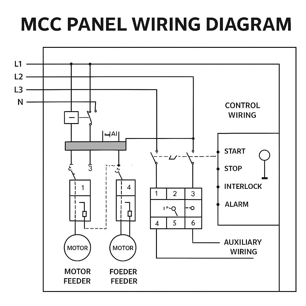
The wiring diagram is central to the MCC Panel Design Guide. It shows how components are connected inside the panel and how control signals interact.
- Power Wiring – Connects main breaker to busbars, then feeders to motors.
- Control Wiring – Handles start/stop commands, interlocks, alarms, and remote control.
- Auxiliary Wiring – For indication lamps, meters, and signaling devices.
A basic MCC wiring layout includes:
- Three-phase power supply feeding the MCC busbar.
- Outgoing feeders connected to individual motor starters.
- Overload relays protecting motors from excessive current.
- Control switches allowing manual or remote operation.
Know more about What Type of Backup Protection is Used for an Alternator?
The wiring diagram must follow IEC 60445 (identification of conductors) for color coding and terminal markings.

MCC Panel Design Guide – Sizing Calculations
Sizing is one of the most important parts of MCC panel design. Incorrect sizing can lead to overheating, failures, or safety hazards.
Motor Feeder Sizing Formula
The current for a motor feeder is calculated as:
I = P / (√3 × V × PF × η)
Where:
- P = Motor Power (W)
- V = Line Voltage (V)
- PF = Power Factor
- η = Efficiency
Example
For a 30 kW motor at 400V, 0.85 PF, and 90% efficiency:
I = 30,000 / (√3 × 400 × 0.85 × 0.9) ≈ 56.7 A
Thus, the feeder should be rated above 60A, with a breaker size of 63A.
Busbar Sizing
Busbars must handle total load current with a safety factor. IEC 61439 defines maximum temperature rise for copper and aluminum conductors.
Total Load Current = Sum of All Motor Currents × Diversity Factor
Know more about IEC Standard for Busbar Sizing
Cable Sizing
Cables must be selected based on current rating, voltage drop, and short-circuit withstand. IEC 60364 is followed for cable selection.
Short-Circuit Rating
The MCC panel must withstand the maximum prospective short circuit current. This is calculated using system fault level at the supply point. Use our free tool to calculate short circuit current here.
Download MCC Panel Design Excel Template
Example Table – MCC Sizing Parameters
| Parameter | Formula / Standard Used | Example Result |
|---|---|---|
| Motor Current | P / (√3 × V × PF × η) | 56.7 A |
| Breaker Size | 1.1 × Motor Current | 63 A |
| Busbar Size | Total Load × Diversity | 500 A |
| Cable Size | IEC 60364 Tables | 25 mm² Cu |
| Short-Circuit Capacity | Based on fault MVA | 25 kA |
MCC Panel Cost in Design Guide
The cost of MCC panels varies widely based on size, configuration, and automation level.
Factors Affecting Cost
- Number of feeders and motors
- Type of starters (DOL, Star-Delta, VFD-based)
- Busbar rating and material (Copper is more expensive than Aluminum)
- Panel enclosure type (Indoor, Outdoor, IP55/IP65)
- Control type (Manual vs PLC-based)
Know more about Types of Faults in Transmission Lines
Cost Estimates
- Small MCC (3–5 motors): USD 3,000 – 7,000
- Medium MCC (10–15 motors): USD 10,000 – 25,000
- Large MCC (20+ motors with VFDs/PLC): USD 40,000 – 100,000+
A cost-benefit analysis is crucial before finalizing the design. Although higher initial investment may be required for advanced systems, long-term savings are realized through reduced downtime and maintenance.
MCC Panel Design Guide for Safety and Reliability
Safety is paramount in MCC panel design. IEC 60204 and IEC 61439 specify minimum safety requirements. Engineers must ensure:
- Proper clearances between live parts.
- Earth bonding for all metallic enclosures.
- Arc fault protection where applicable.
- Use of interlocks to prevent unsafe operation.
- Temperature rise testing and ventilation for heat dissipation.
Reliability comes from selecting high-quality breakers, contactors, and busbar systems. Routine maintenance schedules should be defined at the design stage.
Future Trends in MCC Panel Design Guide
Modern MCC panels are no longer just about motor control. They integrate with digital systems and Industry 4.0 environments.
- Smart MCCs with IoT-enabled monitoring.
- Energy efficiency features like power factor correction.
- Remote monitoring using SCADA and cloud dashboards.
- Modular designs for quick replacement and expansion.
These advancements make MCC panels more efficient, user-friendly, and safer for industrial operations.
Conclusion
The MCC Panel Design Guide is essential for engineers working in electrical design, automation, and industrial power systems. By following IEC standards, creating accurate wiring diagrams, and performing correct sizing calculations, one can design panels that are safe, reliable, and cost-effective.
Know more about Types of Alternator Protection
Costs depend on design complexity, but investing in high-quality MCC panels ensures operational efficiency and long-term savings. With future advancements in digital integration, MCC panels are evolving into intelligent control hubs, far beyond traditional motor control.
Follow Us on Social:
Subscribe our Newsletter on Electrical Insights for latest updates from Electrical Engineering Hub
#MCCPanelDesignGuide, #MCCPanel, #IECStandards, #ElectricalEngineering, #WiringDiagram, #PanelDesign, #MotorControlCenter, #IndustrialElectrical, #MCCWiring, #ElectricalPanels, #EngineeringGuide, #PowerDistribution, #MCCCost, #SizingCalculations, #ElectricalSafety


