
Two 150 kVA single phase transformers are connected in parallel
Problem: Two 150 kVA single-phase transformers are connected in parallel on…
Practical transformer guides for engineers, estimators, and installers: how to size the kVA rating, apply demand and diversity factors, and select protection and conductors that meet code. Start with the guides below, or browse every article underneath.
kVA formulas: Single-phase kVA = V × I ÷ 1000. Three-phase kVA = √3 × V × I ÷ 1000. Calculate the connected load first, then apply demand and diversity factors to avoid oversizing.
Spare capacity: Designers commonly add a margin for future growth, then round up to the next standard kVA rating. Confirm the margin against your project specification.
Protection: In the US, transformer overcurrent protection is covered by NEC Article 450. Primary and secondary protection are sized differently, so use the OCPD chart for the exact rules.
Grounding: Grounding conductor size depends on the supply conductors and the overcurrent device rating. Always verify against the code edition adopted in your jurisdiction.
Problem: Two 150 kVA single-phase transformers are connected in parallel on…

Isolation transformers serve the galvanic isolation in electrical systems by isolating the circuits supply and and secondary side. In single phase electrical wiring, there are three wires hot, neutral, and ground. When there are numerous physically separated devices are connected in the same circuit they may use a similar power line.
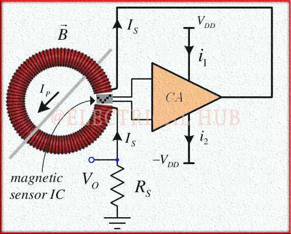
At the heart of the DC current transformer working principle is its core and coil arrangement. Similar to AC transformers, DC current transformers consist of a magnetic core and primary and secondary windings. The primary winding, typically consisting of a single turn or a few turns of a thick conductor, is connected in series with the DC circuit carrying the current to be measured.
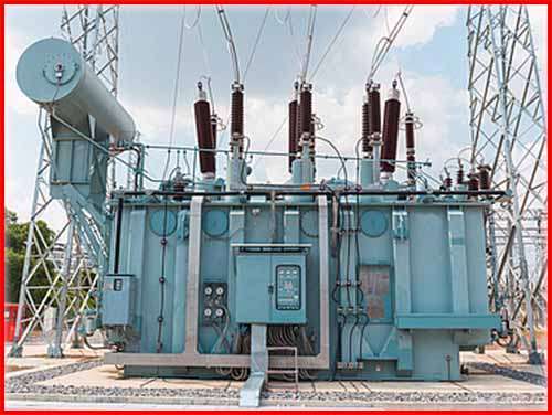
Power transformer manufacturers play a pivotal role in the global energy…
In the field of electrical engineering and energy distribution, power transformer…
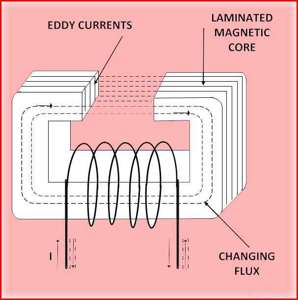
Difference between Hysteresis loss and eddy current loss can be simplified by understanding the types of losses. Hysteresis loss and eddy current loss are two distinct mechanisms of energy dissipation in different situations.
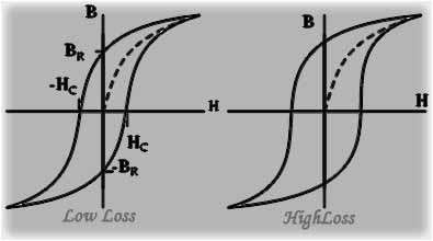
The derivation of the magnitude of hysteresis losses involves analyzing the energy dissipated during a complete cycle of magnetization and demagnetization of a ferromagnetic material.
Hysteresis loss, also known as magnetic hysteresis loss, is a phenomenon that occurs in ferromagnetic materials when they are subjected to cyclic magnetic fields. It refers to the energy dissipated in the form of heat as the magnetic domains within the material undergo repeated alignment and realignment with the changing magnetic field. Hysteresis is a significant factor to consider in various electrical and magnetic applications.
Eddy current loss, also known as Foucault or joule loss, is a phenomenon that occurs when a conductor is exposed to a varying magnetic field, resulting in the generation of circulating currents within the conductor. These circulating currents are known as Eddy currents and are responsible for the dissipation of energy in the form of heat. Eddy current loss can have significant implications in various electrical and magnetic systems.
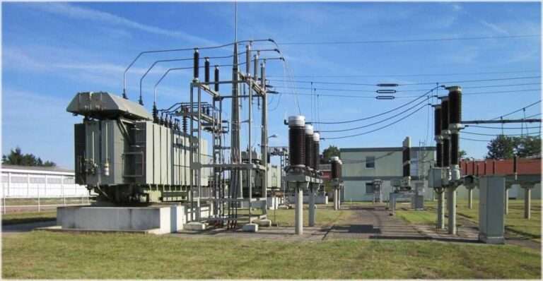
Transformers, the essential devices in power transmission and distribution systems, play a pivotal role in ensuring efficient and reliable electricity supply.
Transformer tests before commissioning are essential in ensuring the safe and reliable operation of power transformers. These tests can help detect potential issues and faults in the transformer, which can be addressed through maintenance or repair before they result in more serious problems.