Electrical Earthing: Important Types & Methods
Table of Contents
What is Electrical Earthing?
Electrical earthing, also known as grounding, is a safety measure in electrical systems that involves connecting electrical equipment and installations to the Earth’s conductive surface.
The purpose of electrical earthing is to create a low-resistance path for electric current to flow into the ground. This is basically to prevent the buildup of excessive voltage and reduce the risk of electrical shock to human life or fire hazards.
In the below picture we can see how the earthing cables from different electrical equipment connect to the main earthing junction box.
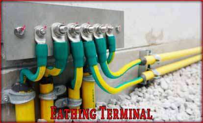
Electrical earthing is achieved by connecting metallic components, such as the electrical panel, appliances, and conductive parts, to a grounding electrode system. Which typically consists of metallic rods or plates buried in the ground.
This connection allows any stray currents or faults to be safely discharged, ensuring the safety of people and equipment.
Types of electrical earthing
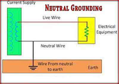
Neutral Earthing:
In this type of electrical earthing, the neutral of the electrical system is directly connected to the earth using a GI wire. It is also known as system earthing and is commonly used in systems with star windings, such as generators, transformers, and motors.
Equipment Earthing
This type of electrical earthing is specifically provided for electrical equipment. The non-current carrying parts, such as the metallic frame of the equipment, are connected to the earth using a conducting wire. In case of a fault, the short-circuit current flows to the earth through this wire, protecting the system from damage.
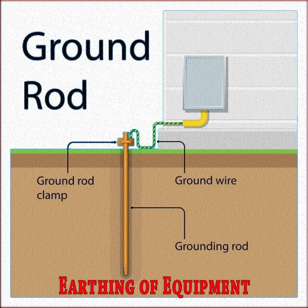
By implementing both neutral earthing and equipment earthing, electrical systems ensure the safety of both the system itself and the connected equipment.
Importance of Electrical Earthing
Electrical Earthing is important in electrical systems for the following reasons:
Safety: It prevents electrical shocks and protects individuals from electrocution. Let’s consider a system which is not earthed as shown in below diagram.
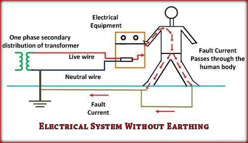
As the person touches the faulty electrical equipment where live wire touching the body of the equipment, will get a shock. As the current with get a path to flow through the body to the ground. While let’s consider as an other example of system where the electrical system is earthed properly.
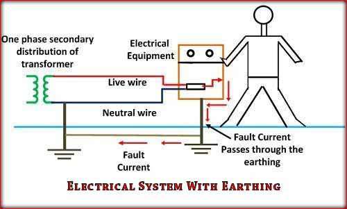
In this system, as the equipment gets faulty, all the fault current goes through earthing wire to the ground. Hence the human life remains safe in a grounded system.
Protection against Faults: It safeguards electrical systems and equipment from damage caused by faults like short circuits and overloads.
Voltage Stabilization: It maintains stable voltage levels, ensuring proper operation of sensitive electronic devices.
Lightning Protection: It safeguards structures and equipment from lightning strikes, reducing the risk of damage and fire.
Equipment Performance: It improves the performance and lifespan of electrical equipment by eliminating stray currents and reducing interference.
Compliance with Standards: It ensures adherence to safety regulations and standards, maintaining system reliability and legal conformity.
Personnel and Property Protection: It safeguards individuals and property from electrical hazards, reducing the risk of injury and damage.
Understanding the importance of earthing and following proper practices is essential for electrical safety and system reliability. Consult professionals for appropriate design and installation.
Electrical Earthing Techniques
There are several techniques of electrical earthing commonly used in electrical systems. Here, I will provide a brief explanation of each type:
Plate Earthing: In this method, a metal plate, usually made of copper or galvanized iron, is buried vertically in the ground. The plate is connected to the electrical system’s earth wire, providing a path for fault currents to flow into the ground.
Rod Earthing: Rod earthing involves the use of a metal rod, often made of copper or a copper-coated material, which is driven into the ground. The rod is connected to the electrical system’s earth wire, allowing fault currents to be safely discharged into the ground.
Pipe Earthing: In pipe earthing, a metal pipe, such as a steel or galvanized iron pipe, is driven vertically into the ground. The pipe is connected to the electrical system’s earth wire, providing an effective grounding path.
Strip Earthing: This method uses a metal strip, typically made of copper or aluminum, buried horizontally in a trench. The strip is connected to the electrical system’s earth wire, allowing fault currents to dissipate into the ground.
Rod-in-Conduit Earthing: Rod-in-conduit earthing involves placing a metal rod inside a PVC conduit, which is then buried in the ground. The rod is connected to the electrical system’s earth wire, providing a reliable grounding path.
Earth Electrode Earthing: This method uses multiple electrodes, such as rods or plates, installed at specific intervals and connected in parallel. It ensures a low-resistance path to the ground and is commonly used in areas with high soil resistivity.
Chemical Earthing: Chemical earthing utilizes a mixture of conductive materials, such as salt and charcoal, to create an enhanced grounding system. It improves the conductivity of the soil and provides a reliable earth connection.
It’s important to note that the choice of electrical earthing method depends on various factors, including soil resistivity, electrical system requirements, and local regulations. Consulting with a qualified professional or an electrical engineer is recommended for determining the most suitable earthing method for a specific application.
Calculating the electrical Earthing Rod Size
Calculating the electrical earthing rod size involves considering factors such as soil resistivity, fault current magnitude, and the duration of fault current. Here is a detailed explanation of the calculations involved:
Soil Resistivity: Determine the soil resistivity in ohm-meter (Ω·m) at the location where the electrical earthing rod will be installed. Soil resistivity testing is typically performed using specialized equipment.
The resistivity value helps determine the rod’s size to achieve a desired resistance-to-ground value.
Allowable Step Potential: The allowable step potential is the maximum voltage a person can be exposed to during a fault condition. It is usually specified by local electrical regulations or standards. The step potential depends on factors such as the duration of the fault and the maximum tolerable current that can pass through the body without causing harm.
Fault Current Magnitude: Determine the expected fault current magnitude that the earthing system needs to handle. This value is typically provided by the electrical system’s design or can be estimated based on the system’s ratings.
Duration of Fault Current: Determine the duration of the fault current for which the earthing system needs to be designed. The duration can be specified by local regulations or standards and may vary depending on the application.
Grounding Resistance Calculation: Calculate the grounding resistance required to limit the step potential to an acceptable level during a fault. The formula for grounding resistance is as below
R = ρ × (2πL) / (A × F)
Where R is the grounding resistance in ohms, ρ is the soil resistivity in ohm-meter, L is the length of the rod in meters, A is the cross-sectional area of the rod in square meters, F is the correction factor considering the duration of the fault current.
Selecting the Rod Size: Based on the calculated grounding resistance, refer to standard tables or manufacturer catalogs to select a suitable rod size. The tables provide the resistance-to-ground values for different rod dimensions, materials, and soil resistivities.
It’s essential to note that electrical earthing rod calculations can be complex and require specialized knowledge. Consulting with a qualified electrical engineer or professional experienced in earthing system design is recommended to ensure accurate calculations and compliance with local regulations and standards.
Follow us on LinkedIn”Electrical Insights” to get the latest updates in Electrical Engineering. You can also Follow us LinkedIn to see our latest posts.
Worth Read Posts
- IEC Standard for Instrument Earthing
- Electrical Earthing Important Types
- Earthing Cable Size as Per IEC
- Plant Factor, Plant Capacity Factor, and Load Factor
- Demand Factor
- Buck Converter Interview Questions
- DC DC Converter Interview Questions
- Transformer Electrical Interview
- Top 30 Op Amp Interview Questions
- Power Electronics Interview Questions


