Electrical Bus Bar: Important Types, Applications, and Benefits
Table of Contents
Introduction
Electrical bus bar is a critical component used in power distribution systems to efficiently conduct and distribute electrical power. As an essential part of electrical installations, understanding the functionality, types, and applications of bus bars is crucial for engineers, electricians, and anyone involved in the field of electrical engineering.
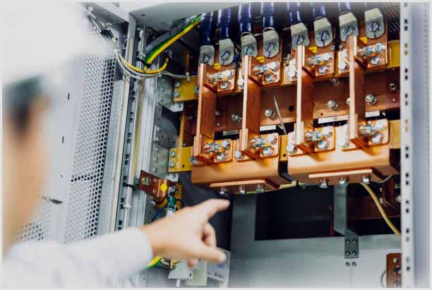
In this guide, we will delve into the world of electrical bus bar, exploring their significance, various types, applications, and the benefits they offer in power distribution systems.
What is an Electrical Bus Bar?
An electrical bus bar, often referred to simply as a bus bar, is a metallic strip or bar used to distribute electrical power within a power distribution system. It serves as a common connection point for multiple circuits, allowing the transfer of electrical current between various components such as generators, transformers, circuit breakers, and distribution panels.
Electrical Bus bars are typically made of copper or aluminum due to their excellent electrical conductivity and high mechanical strength. They are often designed as flat, rectangular-shaped conductors, although other shapes like circular or hexagonal can be used as well.
The choice of material and size of the bus bar depends on the amount of current it needs to carry and the overall power requirements of the system.
Bus bars are installed within an electrical enclosure or a switchgear panel, and they are usually mounted on insulating supports to prevent electrical shorts. The electrical bus bars are connected to the incoming and outgoing terminals of various electrical devices, allowing the flow of electricity between them.
By centralizing the power distribution, bus bars help to simplify the wiring, reduce the complexity of interconnections, and ensure efficient and reliable power transmission throughout the system.
In addition to power distribution, electrical bus bars are also used in electrical grounding systems to provide a low-resistance path for fault currents, ensuring safety and protecting equipment.
They are commonly employed in industrial settings, data centers, electrical substations, and other applications where a large amount of electrical power needs to be distributed and managed effectively.
Key Components & Construction of Electrical Bus Bars
Bus bars are essential components in electrical power distribution systems. They are conductive metal bars or strips used to carry and distribute electrical current within a power distribution system.
Electrical Bus bars are commonly made from materials such as copper or aluminum due to their excellent conductivity and low resistance.
Here are the key components and construction aspects of electrical bus bars:
Material
Copper and aluminum are the most common materials used for electrical bus bars. Copper offers superior electrical conductivity, while aluminum provides a more cost-effective option. The choice of material depends on factors such as current-carrying capacity, cost, weight, and application requirements.
Conductive Surface
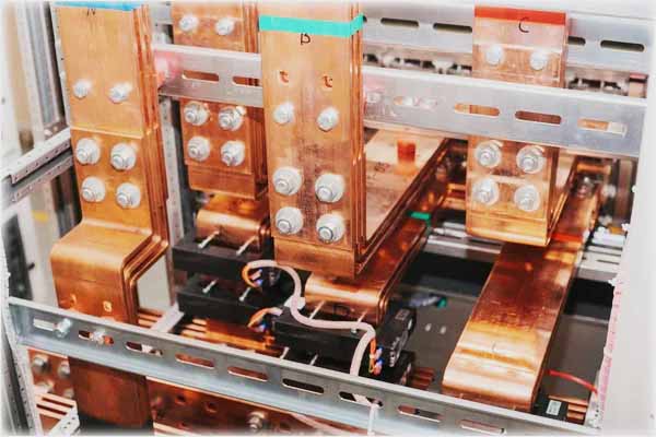
Electrical Bus bars have a flat and smooth conductive surface to ensure efficient electrical contact and reduce resistance. The surface may be bare or coated with materials like tin, silver, or nickel to enhance conductivity, prevent corrosion, or improve solderability.
Shape and Configuration
Bus bars come in various shapes and configurations, including rectangular, circular, or tubular. The shape and size of a bus bar depend on factors such as the current load, voltage level, available space, and mechanical requirements.
Insulation
In certain applications, electrical bus bars require insulation to prevent accidental contact or short circuits. Insulation can be achieved through various methods, including insulating sleeves, coatings, or enclosures.
Bus Bar Supports
Bus bars need to be properly supported and secured within the power distribution system. Insulating supports, such as standoffs or insulators, are used to hold the electrical bus bars in place and maintain the necessary spacing and clearances.
Connection Methods
Bus bars are typically connected to other electrical components or devices using mechanical connectors or bus bar clamps. These connectors ensure a reliable and low-resistance electrical connection between the bus bars and the connected components.
Bus Bar Joints
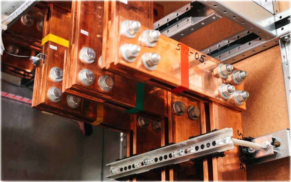
In large power distribution systems, multiple bus bars may need to be connected to accommodate high current loads. Electrical Bus bar joints or splices are used to create electrical continuity and maintain low resistance at these connections. Joints can be made through mechanical bolts, welding, brazing, or specialized connectors.
Cooling and Heat Dissipation
Bus bars can generate heat due to the electrical current flowing through them. In high-current applications, cooling methods such as natural convection, forced air, or liquid cooling may be employed to dissipate heat and prevent overheating of the bus bars.
Labeling and Identification
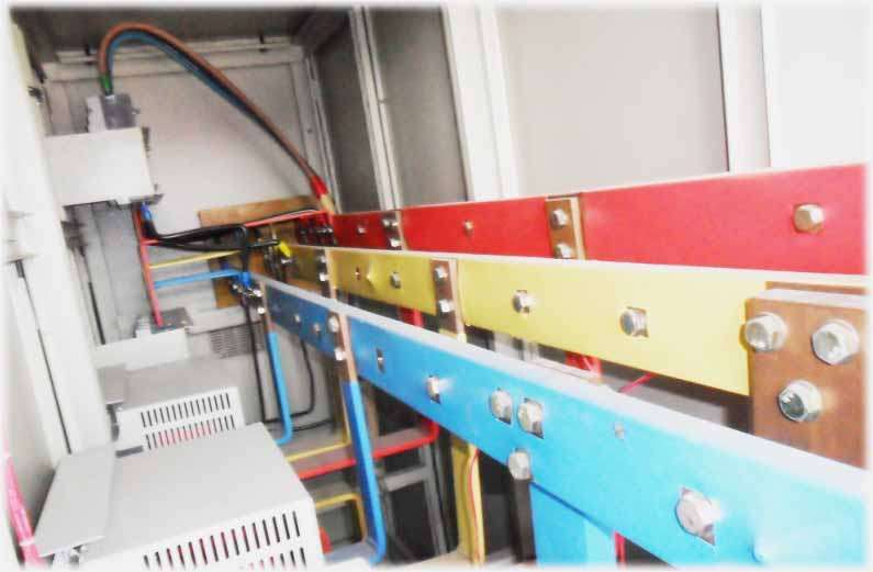
Proper labeling and identification of bus bars are crucial for maintenance, troubleshooting, and safety purposes. Bus bars are often marked with labels, tags, or color codes to indicate their function, voltage rating, current capacity, and phase identification.
Overall, the construction of bus bars involves careful consideration of electrical, mechanical, and thermal aspects to ensure efficient power distribution, reliability, and safety within electrical systems.
Types of Electrical Bus Bar
There are several types of electrical bus bar used in various applications.
Here are some common types:
Single Bus Bar
In this configuration, all the electrical components are connected to a single electrical bus bar. It is a simple and cost-effective design but lacks redundancy, meaning that if the bus bar fails, the entire system can be affected.
Double Bus Bar
This configuration consists of two parallel bus bars. One bus bar is active, carrying the load, while the other serves as a backup or standby bus bar. The double bus bar system provides redundancy, allowing for maintenance or repairs on one electrical bus bar without interrupting power supply.
Main-Tie-Main Bus Bar
This configuration is commonly used in critical power systems. It consists of two independent bus bars, each serving as a main supply for different sections of the system. The tie bus bar connects the two main bus bars and allows for the transfer of power in case one bus bar fails or requires maintenance.
Ring Bus Bar
In a ring bus bar configuration, multiple bus bars are connected in a closed loop or ring-like arrangement. Electrical components are connected to the ring bus bar at various points. This design provides redundancy and allows for easier maintenance as power can flow in either direction within the loop.
Segregated Phase Bus Bar
This type of electrical bus bar is used in high-voltage applications, such as substations and power generation plants. It consists of individual metal enclosures or compartments for each phase of the electrical system, providing insulation and protection against electrical faults.
Sandwich Bus Bar
A sandwich bus bar consists of multiple conductive layers separated by insulating layers. This design allows for higher current-carrying capacity in a compact form factor, making it suitable for applications where space is limited.
These are just a few examples of the different types of electrical bus bars. The choice of bus bar configuration depends on factors such as the power system requirements, redundancy needs, maintenance considerations, and the specific application in which it is being used.
Electrical Bus Bars size calculation
Calculating the size of electrical bus bars involves considering several factors, including the maximum current carrying capacity, voltage drop limitations, temperature rise, and mechanical strength. Here’s a step-by-step guide for sizing electrical bus bars:
Determine the maximum current: Start by determining the maximum current that the bus bar needs to carry. This can be determined by analyzing the electrical load connected to the electrical bus bar or referring to equipment specifications. Make sure to account for future growth and potential increases in current demand.
Current density selection: Determine the acceptable current density (A/mm² or A/in²) for the bus bar material being used. The current density depends on factors such as the material type, temperature rise limits, and electrical code requirements.
Generally, lower current densities are used for higher ambient temperatures or when tighter temperature rise limitations are necessary.
Calculate the cross-sectional area: Divide the maximum current by the selected current density to calculate the required cross-sectional area of the bus bar. For example, if the maximum current is 1000 A and the selected current density is 1 A/mm², the required cross-sectional area would be 1000 mm².
Determine the bus bar shape: Based on the available space and mechanical considerations, select an appropriate electrical bus bar shape, such as rectangular, circular, or tubular. The shape should provide the required cross-sectional area while considering the mechanical strength and space constraints.
Account for skin effect and proximity effect: At high frequencies or with alternating current (AC) applications, skin effect and proximity effect can impact the effective current-carrying capacity of the bus bar.
These effects cause the current to concentrate near the surface of the conductor. To account for these effects, refer to appropriate engineering references or use specialized software tools.
Consider voltage drop: Determine the acceptable voltage drop across the bus bar. This can be based on system requirements, electrical codes, or equipment specifications.
Calculate the voltage drop using the resistance of the selected electrical bus bar material and the anticipated current. Ensure the voltage drop is within the acceptable limits.
Thermal considerations: Evaluate the thermal performance of the bus bar to ensure it can dissipate heat generated during operation. Consider factors such as ambient temperature, temperature rise limitations, and the thermal conductivity of the material.
Verify that the bus bar’s temperature rise remains within acceptable limits to prevent overheating.
Mechanical strength: Assess the mechanical strength requirements of the bus bar, considering factors such as short-circuit currents, vibration, and mechanical stress. Ensure the selected electrical bus bar size can withstand these forces and meets relevant industry standards and safety regulations.
Consult bus bar design guides and standards: Refer to industry design guides, electrical codes, and standards (e.g., IEC, NEC, IEEE) for specific guidelines and requirements related to bus bar sizing, clearance, and insulation.
It is important to note that bus bar sizing is a complex process that may require the expertise of electrical engineers or professionals experienced in power distribution system design. Additionally, local electrical codes and regulations may provide specific requirements that must be considered in the sizing process.
Applications of Electrical Bus Bars
Electrical bus bars find application in various industries and power distribution systems. Here are some common applications:
Power Distribution Systems: Bus bars are extensively used in electrical power distribution systems to distribute electrical power from the main source to different loads.
They provide a centralized and efficient method of carrying high currents and voltages to various electrical equipment such as switchgear, transformers, circuit breakers, and distribution panels.
Switchgear and Circuit Breakers: Bus bars are integral components of switchgear and circuit breaker assemblies. They connect the incoming and outgoing power lines to the switches or breakers, allowing for the control and protection of electrical circuits.
Electrical Bus bars in switchgear and circuit breakers are designed to handle high fault currents and provide reliable electrical connections.
Data Centers: Bus bars are commonly employed in data centers to distribute power to racks and server cabinets. They provide a flexible and scalable solution for power distribution, allowing for easy additions, modifications, and maintenance.
Bus bars in data centers offer high current-carrying capacity and efficient power transmission to meet the demanding power requirements of servers and networking equipment.
Industrial Applications: Electrical Bus bars play a critical role in industrial applications such as manufacturing plants, refineries, and power generation facilities. They are used for power distribution to large machinery, motors, control panels, and other electrical equipment.
Bus bars in industrial settings are designed to handle high currents, withstand harsh environments, and provide reliable electrical connections.
Renewable Energy Systems: Bus bars are utilized in renewable energy systems, including solar power and wind power installations. They are employed in power inverters, combiner boxes, and distribution panels to collect and distribute the generated electricity.
Electrical Bus bars in renewable energy systems ensure efficient power transmission, minimize losses, and support the integration of renewable energy sources into the electrical grid.
Electric Vehicles: Bus bars are essential components in electric vehicles (EVs) for power distribution within the vehicle’s electrical system. They connect the battery pack to various components such as the motor controller, power electronics, and charging system.
Electrical Bus bars in EVs require high current-carrying capacity, low resistance, and efficient heat dissipation to support the high-power demands of electric propulsion systems.
Power Electronics: Bus bars are used in power electronics applications, including motor drives, variable frequency drives (VFDs), and uninterruptible power supplies (UPS). They provide a low-resistance path for high-current connections between power semiconductors, capacitors, and other electronic components.
Electrical Bus bars in power electronics help reduce losses, improve thermal management, and ensure reliable electrical connections.
These are just a few examples of the diverse applications of electrical bus bars. They are versatile components that play a crucial role in efficient power distribution and transmission across various industries and electrical systems.
Electrical Bus Bars advantages and disadvantages
Electrical bus bars offer several advantages and disadvantages, which are important to consider when designing and implementing power distribution systems. Here are some key advantages and disadvantages of electrical bus bars:
Advantages:
Efficient Power Distribution: Bus bars provide a centralized and efficient method for distributing electrical power within a system. They offer low resistance paths for current flow, minimizing voltage drops and power losses.
High Current-Carrying Capacity: Electrical Bus bars are designed to handle high current loads. They have larger cross-sectional areas compared to individual wires, allowing for the transmission of significant electrical currents without overheating.
Space-Saving: Bus bars can be compact and take up less space compared to multiple individual cables or wires. This makes them beneficial in applications with limited space or where neat and organized wiring is required.
Enhanced Reliability: Bus bars offer reliable electrical connections and reduce the number of potential failure points compared to individual cables. They minimize the chances of loose or disconnected connections, reducing the risk of electrical faults and improving system reliability.
Easy Installation and Maintenance: Bus bars simplify installation since multiple connections can be made at once, reducing labor and time. They also facilitate easier maintenance and troubleshooting as the system’s configuration is more accessible and manageable.
Improved Electrical Safety: The use of bus bars can enhance electrical safety by reducing the risk of accidental contact or short circuits. Properly insulated and protected bus bars can minimize the potential for electrical shocks or hazards.
Disadvantages:
Limited Flexibility: Once installed, electrical bus bars are less flexible compared to individual cables. They may not be easily reconfigured or modified, making system changes or expansions more challenging.
Higher Initial Cost: The upfront cost of bus bars can be higher compared to individual cables due to the need for specialized bus bar materials, connectors, and supports. However, in certain cases, the cost savings from reduced labor and material requirements may offset this initial expense.
Thermal Management: Electrical Bus bars can generate heat due to the electrical current flowing through them. Effective heat dissipation and thermal management measures, such as cooling systems or proper bus bar sizing, need to be implemented to prevent overheating and ensure system performance.
Mechanical Strength and Rigidity: Bus bars may require additional mechanical supports and insulation to withstand mechanical stresses, vibrations, and environmental conditions.
Ensuring proper mechanical strength and rigidity can be crucial, especially in applications where the bus bars are subject to mechanical stress or vibrations.
Complexity in Design and Sizing: Designing and sizing electrical bus bars require careful consideration of various factors such as current capacity, voltage drop, thermal performance, and mechanical strength.
Accurate calculations and adherence to industry standards and codes are necessary to ensure safe and reliable operation.
It is important to evaluate these advantages and disadvantages in the context of specific applications and system requirements to determine the suitability of using electrical bus bars.
Future Trends and Innovations in Bus Bar Technology
Bus bar technology continues to evolve to meet the increasing demands of modern power distribution systems.
Here are some future trends and innovations in bus bar technology:
High-Conductivity Materials: Research and development efforts are focused on exploring new materials or composite structures with even higher electrical conductivity than traditional copper and aluminum. This can help reduce resistance and losses in electrical bus bars, improving energy efficiency.
Advanced Cooling Techniques: As power densities increase, effective cooling of bus bars becomes more critical. Future bus bar designs may incorporate advanced cooling techniques such as liquid cooling, phase-change materials, or microchannel cooling to enhance heat dissipation and ensure optimal thermal management.
Integration of Power Electronics: With the growing importance of power electronics in various applications, electrical bus bar technology is expected to evolve to accommodate the integration of power semiconductor devices. Bus bars could be designed to facilitate the direct attachment of power modules, providing efficient electrical connections and optimized thermal pathways.
Miniaturization and Higher Power Density: The trend towards smaller and more compact electronic devices and systems will likely drive the need for miniaturized bus bars. Future innovations may focus on developing bus bars with higher power density, enabling more efficient use of available space and meeting the demands of miniaturized power distribution systems.
Smart and Integrated Bus Bars: Bus bars with built-in sensors, monitoring capabilities, and communication interfaces may become more prevalent. These smart electrical bus bars can provide real-time data on parameters such as current, temperature, and voltage, enabling better system monitoring, predictive maintenance, and improved fault detection.
3D Printing and Additive Manufacturing: The utilization of 3D printing and additive manufacturing techniques offers the potential for complex and customized bus bar designs. This technology allows for the creation of intricate bus bar geometries, optimized current paths, and integrated features, leading to improved performance and reduced manufacturing costs.
Improved Insulation and Safety: Future bus bars may incorporate advanced insulation materials and designs to enhance safety and prevent electrical faults. This includes improved insulation systems, insulation monitoring, and fault detection mechanisms to ensure reliable and safe operation.
Sustainability and Environmental Considerations: There is an increasing focus on sustainability in all aspects of technology. Future electrical bus bar innovations may involve the use of environmentally friendly materials, recycling methods, and energy-efficient manufacturing processes to reduce the environmental impact associated with bus bar production and operation.
These trends and innovations in bus bar technology are driven by the need for higher power densities, improved energy efficiency, enhanced reliability, and the integration of advanced power electronics. As technology advances, bus bars will continue to play a crucial role in efficient power distribution systems, adapting to the evolving needs of various industries and applications.
Conclusion
In conclusion, electrical bus bars are essential components in power distribution systems, offering numerous advantages and benefits. They provide efficient power distribution, high current-carrying capacity, and space-saving solutions.
Electrical Bus bars contribute to reliable electrical connections, simplified installation, and easier maintenance. They also enhance electrical safety and minimize the risk of accidental contact or short circuits.
However, bus bars do come with certain disadvantages, such as limited flexibility, higher initial costs, and the need for proper thermal management and mechanical strength. Designing and sizing bus bars require careful consideration of various factors, including current capacity, voltage drop, thermal performance, and mechanical requirements.
Future trends and innovations in bus bar technology focus on high-conductivity materials, advanced cooling techniques, integration of power electronics, miniaturization, smart features, 3D printing, improved insulation and safety, and sustainability.
Overall, electrical bus bars play a crucial role in efficient power distribution and transmission across industries. They continue to evolve to meet the growing demands of modern power systems, providing reliable and safe solutions for the efficient delivery of electrical power.
Follow us on LinkedIn”Electrical Insights” to get the latest updates in Electrical Engineering. You can also Follow us LinkedIn to see our latest posts.
Frequently Asked Questions
What is the purpose of a bus bar?
A bus bar serves as a common connection point for multiple electrical circuits, allowing the distribution of electrical power within a system. It simplifies wiring, reduces interconnections, and ensures efficient power transmission.
What materials are used to make bus bars?
Copper and aluminum are the most commonly used materials for bus bars due to their excellent electrical conductivity. Copper is often preferred for high-current applications, while aluminum is suitable for low to medium currents.
How are bus bars sized?
Bus bar size is determined by factors such as the amount of current it needs to carry, voltage drop limitations, and thermal considerations. Various design calculations, including current-carrying capacity and temperature rise, are performed to determine the appropriate size.
What are the advantages of using a double bus bar configuration?
The double bus bar configuration provides redundancy, allowing for a backup power supply in case of a failure or maintenance on one bus bar. It minimizes downtime and allows for easy switching between the active and standby bus bars.
Can bus bars be used for grounding?
Yes, bus bars are commonly used in electrical grounding systems. They provide a low-resistance path for fault currents to protect equipment and ensure safety.
How are bus bars protected from electrical faults?
Bus bars are often enclosed in insulating materials or compartments to protect them from electrical faults. In high-voltage applications, segregated phase bus bars are used, which provide individual enclosures for each phase to enhance insulation and fault containment.
Can bus bars be customized for specific applications?
Yes, bus bars can be customized based on the requirements of the application. This includes the shape, size, material, and insulating arrangements to meet specific electrical and mechanical need.
What maintenance is required for bus bars?
Bus bars should be regularly inspected for signs of corrosion, loose connections, or damage. Proper cleaning and tightening of connections may be necessary. Periodic thermographic inspections can help identify any abnormal heating or potential issues.
Can bus bars be used in both AC and DC systems?
Yes, bus bars are used in both AC and DC electrical systems. However, certain considerations, such as skin effect in AC systems or voltage polarity in DC systems, may need to be taken into account during the design.
Are there international standards for bus bar design and construction?
Yes, there are several international standards and guidelines, such as IEC 61439, UL 508A, and NEMA BU 1, which provide specifications and requirements for bus bar design, construction, and testing. Compliance with these standards ensures safety and reliability.

