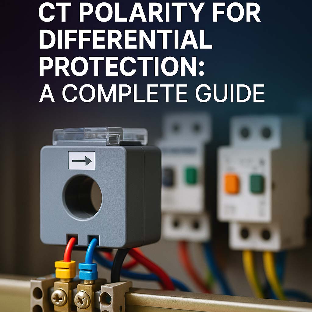
CT Polarity for Differential Protection: A Complete Guide
Current transformers (CTs) play a crucial role in differential protection schemes. One of the most critical aspects of using CTs in these systems is ensuring correct CT polarity for differential protection. Even a minor mistake in polarity can lead to false tripping or failure to detect internal faults in transformers, generators, or busbars.

In this guide, we will explore everything you need to know about CT polarity in the context of differential protection. This includes technical insights, practical guidelines, and real-world considerations. Whether you’re a protection engineer or a student, this article is designed to be clear, informative, and easy to understand.
Why CT Polarity for Differential Protection is Important
Differential protection works on the principle of comparing currents entering and leaving a protected zone. CTs are placed on both sides—typically the primary and secondary sides of a transformer. The differential relay calculates the difference between these two currents. Under normal operating conditions or during external faults, the currents (after being adjusted for turns ratio) should match. If there’s a mismatch, it suggests an internal fault.
Now imagine if one CT is connected with the wrong polarity. The relay will misinterpret the normal current flow as a fault. This is why CT polarity for differential protection must be correctly observed and verified.
Learn more about Overcurrent Protection of Transformer
Understanding CT Polarity
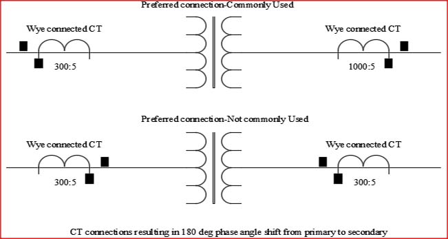
CT polarity refers to the orientation of the CT’s primary and secondary windings. Each CT has a polarity mark—usually denoted as P1 and P2 on the primary, and S1 and S2 on the secondary. Correct polarity means that when current enters P1, the resulting current exits from S1. If this marking is reversed during installation, it can cause major protection issues.
Table: CT Polarity Convention
| CT Side | Marking | Function |
|---|---|---|
| Primary Side | P1, P2 | Direction of main current |
| Secondary Side | S1, S2 | Output to relay circuit |
CT Polarity for Differential Protection in Transformers
Let’s focus on the application in power transformers. In most cases, the differential relay in transformer systems compares current at high-voltage and low-voltage sides. Due to the nature of winding configuration and turns ratio, vector group consideration is important too. But even before dealing with vector group and phase shifts, polarity must be correct.

When installing CTs for differential protection:
- CTs must be installed so their polarity is toward the protected object.
- For transformer protection, this typically means S1 faces the transformer on both HV and LV sides.
- The wiring to the relay must follow the same polarity convention.
If this is violated, even a healthy transformer can trip during load conditions.
Learn more about What are the Three Types of Overcurrent?
Differential Relay Working Principle
To fully grasp the significance of CT polarity, one must understand the working principle of differential protection. A differential relay in transformer measures the vector difference of the two currents. If:
I_diff = I_primary – I_secondary_adjusted
is greater than a predefined setting, the relay operates.
If polarity is reversed, then:
I_diff = I_primary + I_secondary_adjusted
This will cause the relay to trip under normal loading.
Important Note:
During testing, such as PI test of transformer procedure, polarity should be verified. Many misoperations are due to overlooked polarity mismatches.
CT Polarity Errors: Symptoms and Effects
Incorrect CT polarity for differential protection can lead to the following:
- False Tripping: Relay trips when no fault exists.
- Failure to Trip: Internal faults are not detected.
- Increased Relay Operating Time: Misaligned current vectors delay relay decision.
- Incorrect Fault Direction Detection: Particularly in directional protection systems.
The table below summarizes these effects:
| Issue | Likely Cause | Consequence |
|---|---|---|
| False tripping | Reversed CT polarity | Unnecessary outage |
| No tripping on fault | CT polarity mismatch | Asset damage |
| Relay operating slow | Partial polarity error | Delay in isolation |
| Relay unstable | Multiple CT polarity mistakes | Malfunction in protection system |
Learn more about Variable Frequency Drive Interview Questions
CT Polarity Testing Procedure
To ensure proper operation, CT polarity testing must be part of commissioning and maintenance. Here’s a simple field method:
- Inject a small known DC voltage across the primary winding (P1 to P2).
- Measure the resulting secondary output (S1 to S2).
- Use an oscilloscope or multimeter to detect phase orientation.
- Verify that when current flows into P1, it exits from S1.
Many modern relay test sets come with built-in polarity test functions. Always record results for future reference.
Polarity and Vector Group Consideration
For transformer differential protection, vector group is a big factor. For example, a Dyn11 transformer introduces a 30° phase shift. The CT connections must compensate for this. While vector group correction is done via relay settings, polarity must still be correct physically. Errors in either can lead to faulty operation.
In this context, IEC Standard for Protection Relays provides detailed guidelines for CT and VT selection, including polarity and phase shift considerations. Always ensure your CT wiring complies with the standard.
Learn more about Motor Overload Setting Table
Tips to Ensure Correct CT Polarity
- Follow manufacturer markings carefully.
- Label CT terminals clearly during installation.
- Use color-coded wires for S1 and S2.
- Perform polarity checks during differential relay calculation stages.
- Document CT orientation for future maintenance.
- Use testing tools that validate polarity dynamically.
Real-World Example: Transformer Tripping Due to CT Polarity
At a 132kV substation, a newly commissioned 40MVA transformer began tripping on differential protection under no load. After checking wiring and relay settings, it was discovered that the S1 and S2 terminals were swapped on one of the CTs. Once corrected, the issue was resolved. This highlights how critical CT polarity is—not just theoretically, but practically.
CT Polarity in Bus Differential Protection
Bus differential protection also relies heavily on CT polarity. Each feeder and incomer to the bus must have CTs oriented correctly toward the busbar. If one CT is reversed, it will add current during a fault, masking the differential current and causing the relay to underperform. Unlike transformer protection, bus protection doesn’t deal with vector shifts, so CT polarity becomes even more critical.
Learn more about IEC Standard for Protection Relays
Role of CT Polarity in Overcurrent Protection
Although not as sensitive to polarity as differential protection, overcurrent relays can still be affected. Especially in directional overcurrent applications, polarity defines fault direction. For applications involving types of overcurrent protection (instantaneous, inverse-time, etc.), CT polarity must be correct to avoid nuisance tripping or underreaching.
Summary: Why CT Polarity Cannot Be Ignored
To conclude, CT polarity for differential protection is a foundational concept. It impacts relay operation directly. Incorrect polarity can cause system instability, unnecessary outages, and failure to detect internal faults. Whether you’re working on a simple transformer differential relay or a complex busbar scheme, CT polarity should be verified and documented.
Before energizing any differential protection scheme, always check:
- CT polarity
- Vector group correction
- CT ratio and class
- Relay wiring consistency
By doing so, you enhance system reliability and meet the criteria set by IEC Standard for Protection Relays. Always treat polarity checks as seriously as relay settings or transformer testing.
Follow Us on Social:
Subscribe our Newsletter on Electrical Insights for latest updates from Electrical Engineering Hub
#CTPolarity, #DifferentialProtection, #ElectricalEngineering, #CTConnection, #PowerSystemProtection, #RelayProtection, #CTTesting, #ProtectionRelays, #CurrentTransformer, #ElectricalSafety, #EngineeringGuide, #SubstationDesign, #CTWiring, #TransformerProtection, #CTPolarityTesting


Incredible points. Sound arguments. Keep up the amazing spirit.
I could not refrain from commenting. Well written!