ESP12F Pinout: An Important Guide
The ESP12F module, based on the ESP8266 chip, is one of the most popular Wi-Fi-enabled microcontroller modules in IoT development. Known for its compact size, high performance, and affordability, the ESP12F is an upgraded version of the ESP12E, offering improved RF performance and reliability. In this article, we’ll dive into the ESP12F pinout, providing a detailed technical breakdown of each pin, its functionality, and how to use it in your projects.
Whether you’re a beginner or an experienced IoT enthusiast, understanding the ESP12F pinout is essential to leveraging the full potential of this module.

Table of Contents
Table of Contents
What is ESP12F?
The ESP12F is a Wi-Fi module powered by the ESP8266 chip, which features a 32-bit Tensilica Xtensa LX106 processor. It supports multiple GPIO pins, UART, SPI, I2C, and PWM, making it a versatile choice for IoT applications like home automation, wireless monitoring, and smart devices.
The ESP12F pinout enhances the usability of the ESP8266 chip by providing easy access to its features.
For more information about ESP8266 modules, check out related guides like ESP8266 Pin Diagram and ESP8266 GPIO Pins.
ESP12F Pinout Overview
The ESP12F module consists of 22 pins, including power pins, communication interfaces, and GPIO pins. Below is a high-level breakdown of the pinout and its functions:

Key Features of the ESP12F Pinout
- 22 accessible pins
- 16 GPIOs (General Purpose Input/Output)
- Support for UART, SPI, and I2C interfaces
- Integrated ADC (Analog to Digital Converter)
- Enhanced RF performance compared to ESP12E
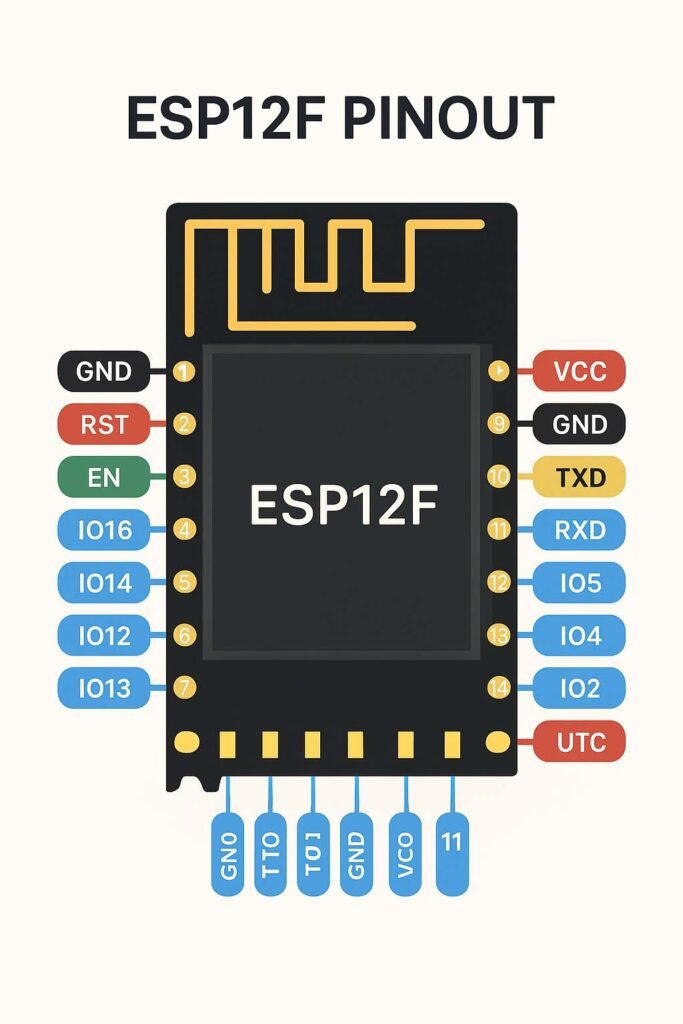
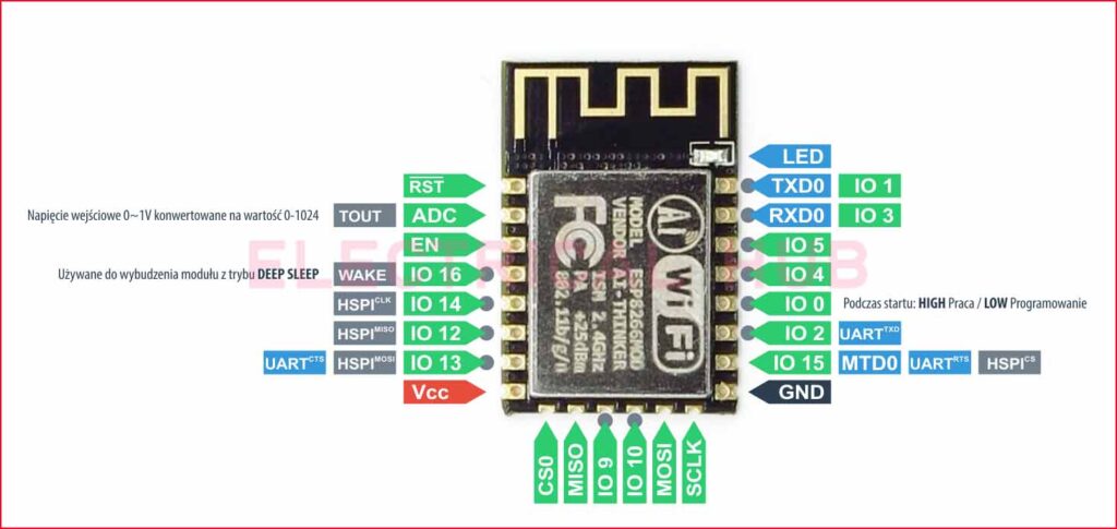
Below is the ESP12F pinout diagram and the detailed functionality of each pin.

ESP12F Pinout Diagram
Before we dive into the details of each pin, it’s crucial to familiarize yourself with the ESP12F pinout diagram. The pin configuration allows developers to connect various peripherals and sensors effectively.
ESP12F Pinout Pin Description
Here’s a detailed explanation of the ESP12F pinout:
VCC (Power Supply Pin)
Provides power to the ESP12F module.
Voltage range: 3.0V–3.6V (typically 3.3V).
GND (Ground)
Connects the module to the system ground.
Must be connected to the ground rail of your circuit.
EN (Enable)
Used to enable or disable the chip.
Connect to VCC through a pull-up resistor to enable the module.
GPIO Pins
ADC (Analog to Digital Converter)
Pin: ADC0
- Converts analog input (0–1V) to a digital signal.
- Ideal for reading sensors like temperature, light, or potentiometers.
UART Pins
SPI Pins
Supports Serial Peripheral Interface (SPI) for high-speed communication.
Commonly used pins: MISO (GPIO12), MOSI (GPIO13), SCK (GPIO14), CS (GPIO15).
I2C Pins
ESP12F Pinout Connections
Here’s how to connect your ESP12F module in various scenarios:
Power Supply
- Provide a regulated 3.3V to the VCC pin.
- Use a capacitor (e.g., 10uF) across VCC and GND for stable operation.
Reset and Enable
- Connect the EN pin to VCC via a pull-up resistor.
- Add a push-button to the RST pin for manual resetting.
Programming Mode
- Pull GPIO0 LOW during boot to enable flashing mode.
- Ensure proper connections with an external USB-to-UART converter.
Deep Sleep Mode
- Connect GPIO16 to the RST pin to enable wake-up from deep sleep.
ESP12F Pinout Applications
The versatility of the ESP12F module makes it suitable for a wide range of IoT projects:
Home Automation
Control lights, fans, and appliances using Wi-Fi.
Wireless Monitoring
Monitor environmental parameters like temperature and humidity.
Know more about applications of schmitt trigger
Smart Devices
Tips for Working with the ESP12F Pinout
- Power Stability
- Use a stable 3.3V regulator, as fluctuations can cause unexpected resets.
- Breadboard Use
- Use an adapter board for easy connection to a breadboard.
- GPIO Limitations
- Avoid using GPIO6 to GPIO11 for general-purpose tasks, as they are reserved for flash memory.
- Proper Pull-Up/Pull-Down Resistors
- Use appropriate resistors on GPIO pins to ensure proper operation during boot.
Frequently Asked Questions (FAQs)
1. What is the maximum current consumption of the ESP12F module?
The ESP12F can draw up to 170mA during transmission. Ensure your power source can handle this.
2. Can I use the ESP12F with Arduino IDE?
Yes, the ESP12F is fully compatible with Arduino IDE. Check out our guide on ESP8266 Arduino for step-by-step instructions.
3. How do I flash firmware to the ESP12F?
You can flash firmware using a USB-to-UART converter. Pull GPIO0 LOW during boot to enter flashing mode.
Conclusion
The ESP12F pinout is the backbone of this powerful Wi-Fi module, offering a range of functionalities that cater to diverse IoT applications. By understanding the pins and their configurations, you can unlock the full potential of the ESP12F and build efficient, reliable projects.
For more insights into ESP modules and related topics, explore our detailed guides:
Start experimenting with the ESP12F and bring your IoT ideas to life!
What is the difference between ESP12 and ESP12F?
ESP-12F is an improved version of ESP-12 with better PCB antenna design, higher stability, and improved Wi-Fi performance compared to the original ESP-12.
How to program ESP12F module?
ESP-12F can be programmed using Arduino IDE or ESP-IDF via a USB-to-Serial adapter (e.g., FTDI), connecting GPIO0 to GND for flash mode.
What is the max current for ESP12F?
The ESP-12F typically consumes up to 170–200 mA during Wi-Fi transmission and about 20–30 µA in deep sleep mode.
What is the difference between ESP01 and ESP12F?
ESP-01 has only 2 GPIOs with limited flash memory, while ESP-12F offers 11+ GPIOs, more flash, and better antenna performance.
Which ESP is better?
ESP-12F is better than ESP-01 for projects needing more GPIOs and stability, while ESP32 is overall superior for performance and features.
What is the most powerful ESP board?
The ESP32 series is the most powerful, offering dual-core processors, Bluetooth, Wi-Fi, more GPIOs, and higher performance than ESP8266 boards.
How to flash ESP12F?
To flash ESP-12F, connect via USB-to-Serial adapter, hold GPIO0 low during reset to enter bootloader, and upload firmware from Arduino IDE or esptool.
What is the frequency of the ESP12F Crystal?
The ESP-12F module uses a 26 MHz external crystal oscillator for its Wi-Fi and processor clock.
How to connect ESP module to Arduino?
Use SoftwareSerial or hardware serial pins, connect TX-RX cross, power at 3.3V, and use logic level shifting if needed for safe communication.
What are the different versions of ESP-12?
ESP-12 variants include ESP-12, ESP-12E, ESP-12F, and ESP-12S, differing in antenna design, stability, and pin arrangement.
What is the difference between the 12 F and 12 E?
ESP-12F has an optimized antenna and better RF performance than ESP-12E, but both have the same pinout and flash size.
What is the difference between ESP12F and ESP07?
ESP-12F has an onboard PCB antenna, while ESP-07 comes with an external antenna connector for longer Wi-Fi range.
What is the spec of ESP-12F?
ESP-12F features the ESP8266EX chip, 4 MB flash, 802.11 b/g/n Wi-Fi, up to 170 mA TX current, 11+ GPIOs, and 26 MHz crystal.
Follow Us on Social:
Subscribe our Newsletter on Electrical Insights for latest updates from Electrical Engineering Hub
#ESP12F, #ESP12FPinout, #ESP8266, #IoTModule, #ESP12FTutorial, #PinoutGuide, #ESP8266Projects, #WirelessModule, #ESP12FDiagram, #IoTDevelopment, #WiFiModule, #Microcontroller, #ESP8266Pinout, #ESP12FDetails, #CircuitDesign


Great breakdown of the ESP12F pinout! This guide will definitely help me when working on my next project. Thanks for the clear explanations and visuals!
Great post! The detailed pinout explanation for the ESP12F is incredibly helpful for beginners. I appreciate the clear diagrams and the tips on how to utilize each pin effectively. Looking forward to more posts like this!
Great guide on the ESP12F pinout! The detailed explanations really help in understanding how to effectively use each pin for various projects. I appreciate the clear diagrams as well – they make it much easier to visualize everything. Looking forward to more posts like this!