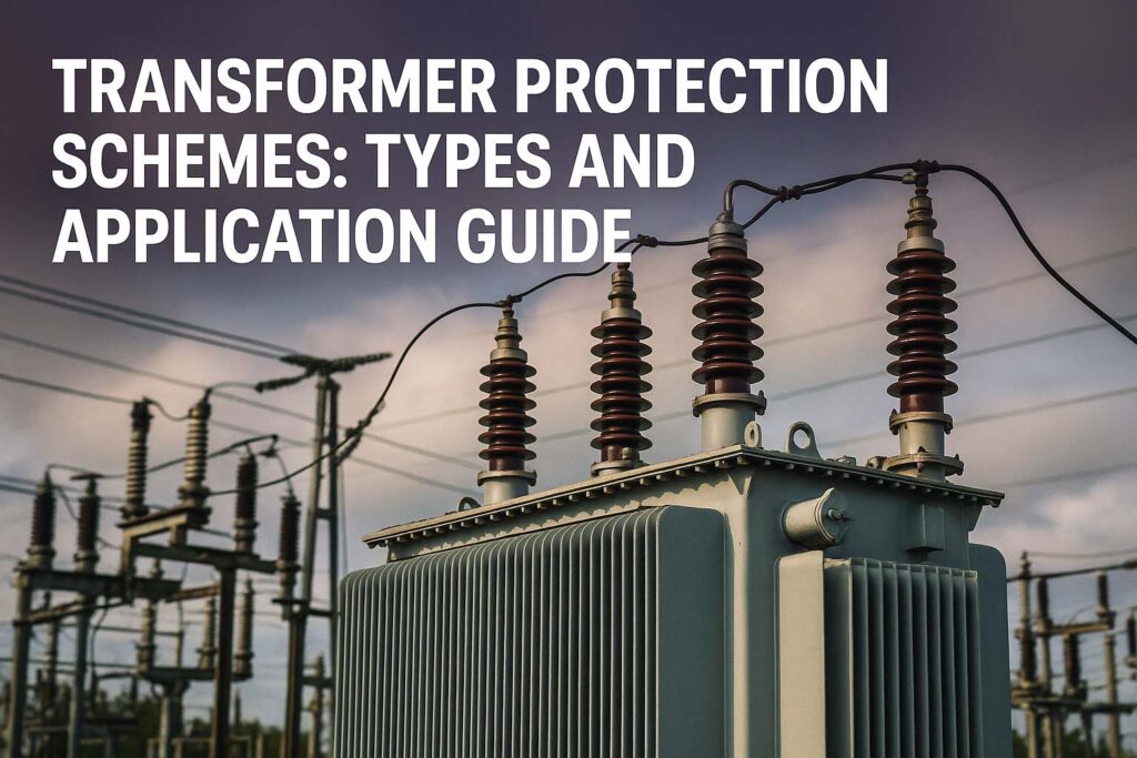
Transformer Protection Schemes: Types and Application Guide
Transformer protection schemes are essential for ensuring the safety, reliability, and efficiency of electrical power systems. Transformers are critical components in transmission and distribution networks. They operate continuously under varying electrical and environmental conditions. Any fault in a transformer, if not detected early, can result in catastrophic failure, prolonged outages, and financial loss. Therefore, implementing effective protection schemes is crucial.

This article explores different types of transformer protection schemes, their applications, and the key considerations in selecting the right scheme for different transformer setups.
What Are Transformer Protection Schemes?
Transformer protection schemes refer to the set of protective relays, sensors, and logic circuits designed to detect internal and external faults in a transformer. These schemes isolate the faulty transformer from the system to prevent equipment damage and ensure personnel safety.
The main objectives of transformer protection are:
- Detecting faults quickly
- Minimizing damage to the transformer
- Ensuring system stability and continuity
- Preventing fire or oil leakage hazards
Common types of faults include winding short circuits, insulation breakdown, core faults, overloading, and external system disturbances.
Types of Transformer Protection Schemes
1. Differential Protection Scheme
Differential protection is one of the most widely used transformer protection schemes. It is based on Kirchhoff’s Current Law (KCL) which states that the sum of currents entering and leaving the transformer must be equal under normal operating conditions.
When a fault occurs inside the transformer, such as winding-to-winding or winding-to-core short circuit, the current balance is disturbed. The differential relay detects this unbalance and trips the circuit breaker.
Applications:
- Used in large power transformers (typically above 5 MVA)
- Provides fast and selective protection
- Effective against internal faults
Key Feature:
- Current transformers (CTs) are placed on both the primary and secondary sides
| Parameter | Value/Notes |
|---|---|
| Protection Time | 30 to 60 milliseconds |
| Sensitivity | High |
| Zone of Protection | Transformer internal windings |
| Cost | Moderate to High |
Know more about Differential Protection of Transformer
2. Overcurrent Protection
Overcurrent protection is simple and cost-effective. It protects the transformer from excessive current caused by overloads or external faults.
This scheme uses time-inverse overcurrent relays connected to the secondary side. These relays trip the transformer when the current exceeds a set threshold for a certain duration.
Applications:
- Distribution transformers (up to 2.5 MVA)
- Backup protection in grid-connected systems
Limitation:
- Cannot detect internal winding faults
- May respond slowly to internal failures
| Parameter | Value/Notes |
|---|---|
| Protection Time | 1 to 2 seconds |
| Cost | Low |
| Reliability | Moderate |
| Zone Covered | External faults |
Know more about High Impedance Busbar Protection
3. Buchholz Relay Protection
Buchholz relay is a gas-actuated protection device specifically used for oil-immersed transformers. It is installed between the main tank and the conservator. When internal arcing or insulation failure occurs, gases are released which activate the Buchholz relay.
Applications:
- Power transformers with conservator tanks
- Detects incipient (slow-developing) faults
Key Advantages:
- Sensitive to both minor and major internal faults
- Provides early warning signals
| Fault Type | Detection Capability |
|---|---|
| Inter-turn Fault | Yes |
| Core Fault | Yes |
| Oil Level Drop | Yes |
| External Fault | No |
4. Restricted Earth Fault (REF) Protection
Restricted earth fault protection detects earth faults within the protected zone of the transformer winding. It is more sensitive than standard earth fault protection and uses the vector sum of CT currents to detect fault current to earth.
Applications:
- Transformers with star point grounding
- Used in conjunction with differential protection
Know more about What Causes a Motor to Overload?
Characteristics:
- Fast fault detection within a limited region
- Requires accurate CT calibration
| Parameter | Details |
|---|---|
| Sensitivity | High |
| Response Time | Fast |
| Zone Coverage | Specific winding region |
5. Temperature-Based Protection
Temperature-based protection schemes use RTDs (Resistance Temperature Detectors) and oil temperature sensors to monitor the temperature of transformer windings and oil. If the temperature exceeds a preset value, alarms or trips are initiated.
Applications:
- All types of transformers
- Ideal for overload protection
Benefits:
- Prevents thermal damage
- Allows pre-emptive maintenance actions
6. Sudden Pressure Relay Protection
Sudden pressure relay monitors the rate of pressure rise in the transformer tank. A sudden increase indicates an internal arcing fault. This relay operates faster than a Buchholz relay for such faults.
Know more about IEC Standard for Differential Protection
Applications:
- Power transformers in critical installations
- Complementary to Buchholz protection
Key Features:
- Detects high-energy internal faults
- Fast acting (less than 10 ms)
Additional Protection Schemes
Apart from the primary types, other schemes are also used in modern transformers:
- Neutral Earthing Protection: Monitors earth current at the neutral point
- Voltage-Based Protection: Includes overvoltage and undervoltage relays
- Harmonic Detection: Identifies internal faults through harmonic content in current
These schemes are often combined to form a comprehensive protection system.
Choosing the Right Transformer Protection Scheme
Selecting the correct protection scheme depends on various factors:
| Criteria | Recommended Protection |
|---|---|
| Transformer Size | Differential, REF, Overcurrent |
| Voltage Class | Buchholz, Pressure Relay |
| Grounding Configuration | REF, Earth Fault Relay |
| Location (Indoor/Outdoor) | Oil Temp, Pressure, Fire Detection |
| Cost Sensitivity | Overcurrent, Temperature Monitoring |
| Criticality of Operation | All-inclusive Scheme |
For large substations or generation transformers, advanced digital relays are used. These relays offer features like disturbance recording, remote monitoring, and adaptive settings.
Know more about What is the Protection Scheme of an Alternator Against Inter Turn Fault?
Why Are Transformer Protection Schemes Important?
Without protection schemes, even minor faults can escalate into serious issues. Some critical consequences of unprotected transformers include:
- Prolonged Blackouts: Power supply disruption for hours or days
- Fire Hazards: Oil-based transformers can catch fire
- Costly Repairs: Replacing a transformer can cost hundreds of thousands of dollars
- Safety Risks: High voltage equipment can be dangerous if not properly isolated during faults
Proper protection also extends the operational life of the transformer and maintains power quality across the grid.
Conclusion
Transformer protection schemes are not optional—they are essential. They safeguard your infrastructure, reduce downtime, and prevent potentially disastrous failures. From differential and overcurrent to Buchholz and earth fault protection, each scheme serves a specific purpose and complements the others.
The best approach is often a layered one—using multiple schemes to create redundancy and cover all possible failure modes. As transformer technology evolves, so do protection methods, with modern digital relays offering intelligent, adaptive, and remote-controlled protection.
Follow Us on Social:
Subscribe our Newsletter on Electrical Insights for latest updates from Electrical Engineering Hub
#TransformerProtection, #ElectricalEngineering, #PowerTransformer, #ProtectionRelay, #SubstationDesign, #TransformerSafety, #DifferentialProtection, #OvercurrentProtection, #RelayCoordination, #TransformerTesting, #HighVoltageEngineering, #EnergySystems, #GridProtection, #PowerSystemEngineering, #ElectricalSafety


Oh my goodness! an amazing article dude. Thank you However I’m experiencing situation with ur rss . Don’t know why Unable to subscribe to it. Is there anybody getting equivalent rss problem? Anyone who is aware of kindly respond. Thnkx