High Impedance Busbar Protection Explained with Example Calculations
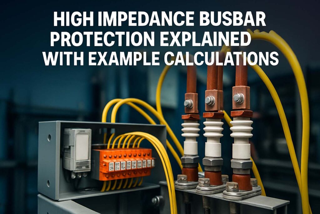
High Impedance Busbar Protection is a proven method used in power systems to safeguard busbars from internal faults. Busbars act as a central point in a substation where several circuits meet. If a fault occurs at the busbar, it affects multiple feeders or transformers, making it critical to clear the fault quickly and selectively.
Table of Contents
Table of Contents

This article breaks down the concept of high impedance busbar protection in simple terms. We’ll explore how it works, why it’s used, and how calculations are done using real-world examples. If you’re an electrical engineer, technician, or student looking to understand this system, this guide offers clear explanations and practical insights.
What is High Impedance Busbar Protection?
High impedance busbar protection is a type of differential protection scheme. It monitors the current entering and leaving a busbar. Under normal operation, the sum of these currents is zero. If there’s an internal fault, this balance is disturbed, and the protection system operates to trip the breakers.
The term “high impedance” refers to the use of a high impedance element—usually a stabilizing resistor and a voltage-setting resistor—in the relay circuit. This approach ensures that only internal faults cause the relay to trip.
Why Use High Impedance Protection?
Busbars are at the core of power distribution systems. A fault here can cascade through the system. High impedance busbar protection is chosen for several reasons:
- Fast operation: It clears faults in milliseconds, minimizing equipment damage.
- High stability: It remains stable during external faults, even with CT saturation.
- Simplicity: It is a straightforward method, widely understood and trusted.
- Reliability: It’s known for dependable fault detection and low nuisance tripping.
Know more about Differential Protection of Transformer
Basic Components of a High Impedance Busbar Protection Scheme
Here are the main components involved:
- Current Transformers (CTs): Installed on each incoming and outgoing line.
- Differential Relay: Compares the current sum and issues a trip if a fault is detected.
- Stabilizing Resistor: Limits the current through the relay during CT saturation.
- Non-linear Resistor (Metrosil): Protects the relay from high voltage.
- Trip Relays & Breaker Control Circuits: Initiate the actual disconnection.
All CTs must have identical ratios and be properly matched for accuracy. This ensures the differential protection operates correctly.
How High Impedance Busbar Protection Works
Let’s walk through the working principle:
Under normal load conditions, the current entering and leaving the busbar through all CTs is balanced. The net current through the differential relay is zero.
During an external fault, one or more CTs may saturate. High impedance in the circuit ensures minimal relay current to prevent false tripping.
During an internal fault, there is a genuine imbalance. The relay detects the voltage across its impedance and operates if it exceeds the set limit.
Stabilizing resistor helps to hold off false tripping by creating a high voltage threshold.
Know more about What is a Programmable Logic Controller (PLC) and How Does it Work?
Key Equations in High Impedance Busbar Protection
Protection design involves a few essential equations. The most important are:
1. Relay Operating Voltage:
V = I_fault × R_total
Where:
- V is the voltage across the relay impedance
- I_fault is the fault current flowing through the CT secondary circuit
- R_total is the total impedance of the relay circuit (relay, wiring, and stabilizing resistor)
2. Minimum Operating Voltage (V_set):
V_set = (n × If_max × Rct)
Where:
- n is the number of CTs
- If_max is the maximum through-fault current
- Rct is the CT secondary winding resistance
This ensures the relay only operates for internal faults.
Know more about Earthing Transformer Working Principle
Example Calculation of High Impedance Busbar Protection
Let’s look at a real-world case:
System Data:
- Number of circuits (CTs): 4
- CT Ratio: 1000/1
- CT secondary resistance (Rct): 1 Ω
- Maximum external fault current (If_max): 5000 A
- Desired safety margin: 2
Step 1: Calculate Maximum Secondary Current
I_sec = If_max / CT ratio = 5000 / 1000 = 5 A
Step 2: Set Operating Voltage (V_set)
V_set = n × I_sec × Rct × safety_margin
       = 4 × 5 × 1 × 2 = 40 V
Step 3: Select Stabilizing Resistor
Assume relay resistance is negligible.
R_total = V_set / I_sec = 40 / 5 = 8 Ω
So, you need a stabilizing resistor of at least 8 Ω.
Step 4: Select Metrosil
Ensure the metrosil can absorb voltage above V_set during heavy internal faults. Typically, it’s rated above 1.5 × V_set = 60 V in this case.
Advantages of High Impedance Busbar Protection
This method has stood the test of time for good reason:
- Immunity to CT Saturation: High impedance blocks spurious relay operation.
- Clear Zone Discrimination: Helps detect exactly which section of the busbar is faulty.
- Cost-effective: No need for complicated numerical relays in simple setups.
- Suitable for older substations: Easily integrates with legacy equipment.
Limitations of High Impedance Busbar Protection
Despite its benefits, this method isn’t perfect:
- CT Matching Required: Mismatched CTs can cause incorrect operation.
- No Backup for External Faults: The scheme is selective and may not back up for line faults.
- Not Ideal for Ring Bus or Mesh Configurations: Complex configurations need numerical or low-impedance protection.
Know more about IEC Standard for Differential Protection
Comparison: High vs Low Impedance Busbar Protection
| Feature | High Impedance | Low Impedance |
|---|---|---|
| Complexity | Simple | Complex (uses numerical relays) |
| CT Matching | Required | Not strictly required |
| CT Saturation Handling | Excellent | Good (uses algorithms) |
| Speed | Very Fast | Fast |
| Application | Single or double busbar | All busbar types |
| Cost | Lower | Higher |
Best Practices for Implementing High Impedance Busbar Protection
- Always test and match CTs for ratio and polarity.
- Ensure wiring resistance is low and stable.
- Use quality stabilizing resistors and metrosils with known ratings.
- Periodically test the relay operation using secondary injection.
- Label all CTs and circuits clearly for easy maintenance.
Know more about What is the Protection Scheme of an Alternator Against Inter Turn Fault?
Final Thoughts
High Impedance Busbar Protection remains a dependable choice for many substations. Its simplicity, high-speed operation, and immunity to CT saturation make it ideal for small to medium substations. While it’s not suitable for complex or dynamic systems, it’s perfect where reliability and speed are crucial.
By understanding its operation, performing accurate calculations, and following best practices, engineers can ensure reliable protection for the heart of their power systems—the busbar.
Follow Us on Social:
Subscribe our Newsletter on Electrical Insights for latest updates from Electrical Engineering Hub
#HighImpedanceProtection, #BusbarProtection, #DifferentialProtection, #PowerSystemProtection, #ElectricalEngineering, #RelayCoordination, #ProtectionRelay, #SubstationDesign, #FaultCurrent, #ElectricalSafety, #ImpedanceCalculations, #TransformerProtection, #HVProtection, #GridProtection, #RelaySettings


