Ground Loop Prevention in Instrumentation Systems – IEC Guidelines and Best Practices
Ground loops are among the most common and stubborn problems in instrumentation systems. They create errors in measurements, inject unwanted noise, and sometimes even damage equipment. In industries where accurate data is the backbone of operations, ignoring ground loop issues can lead to unreliable processes and costly downtime. Preventing these loops requires both practical techniques and adherence to international standards, with the ground loop IEC guidelines providing the most recognized framework.
Table of Contents
Table of Contents

When multiple instruments share different grounding points, unwanted circulating currents can flow through shielding or signal cables. This current is what we call a ground loop. Such loops distort sensitive signals, reduce accuracy, and often create safety risks. The good news is that with proper grounding design, isolation methods, and testing protocols, these problems can be controlled.
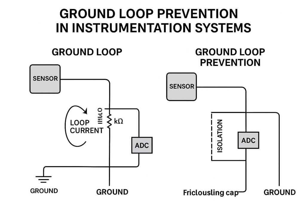
Before we go deeper into IEC recommendations, let us start with a quick overview of the problem. Ground loops happen when there is more than one return path to ground. Since potential differences exist between two grounding points, current flows in the loop, creating voltage drops that directly appear as noise in analog signals. This makes it difficult for sensors and controllers to differentiate between genuine process signals and interference.
Key Takeaways
- Ground loops are formed by multiple grounding paths in instrumentation systems, leading to noise and safety risks.
- Ground loop IEC recommendations emphasize single-point earthing, shield grounding, and equipotential bonding.
- Isolation techniques like optical isolation and transformer isolation are effective ways to break ground loops.
- Testing methods, including loop resistance and induced voltage checks, help detect and mitigate issues.
- Following IEC earthing requirements ensures compliance, safety, and reliable instrumentation performance.
Know more about IEC Standard for Battery Charger – Complete Technical Guide
What is a Ground Loop?
A ground loop is an unwanted electrical path formed when equipment in an instrumentation system is connected to ground at more than one point. This condition allows current to circulate through the grounding conductors, shields, or signal cables. The main cause is potential difference between the two or more grounding points.
In analog instrumentation, even a few millivolts of unwanted voltage from ground loops can disrupt sensor accuracy. For example, in a 4-20mA loop used in process control, a ground loop of just 50mV could cause an error of nearly 0.25mA, leading to false readings.
The problem becomes more critical in high-frequency systems, such as those using digital signals, where ground loop currents may introduce electromagnetic interference. These distortions can corrupt communication protocols, resulting in false data transfer between field devices and controllers.
Common Causes of Ground Loops in Instrumentation
- Multiple earth connections between sensors and control panels
- Improper shield termination of signal cables
- Different grounding potentials in remote system installations
- Sharing of grounding paths with power equipment
- Faulty bonding of metallic enclosures and raceways
Know more about Top Electrical Engineering Software: AutoCAD, ETAP, MATLAB Reviewed
Effects of Ground Loops
- Noise in analog signals
- False alarms and wrong instrumentation readings
- Damage to sensitive circuits due to circulating current
- Poor electromagnetic compatibility (EMC) performance
- Reduced reliability of industrial control systems
IEC Recommendations for Ground Loop Prevention
The ground loop IEC guidelines form part of broader international standards that cover industrial earthing and bonding practices. The IEC 60364 earthing standard and related documents provide detailed methods for preventing unwanted loops in instrumentation systems. For in-depth insights, you may also explore our guide on instrument earthing IEC standard.
IEC emphasizes that correct design of grounding systems should start from project planning and continue through installation and commissioning. The following recommendations form the backbone of loop prevention:
1. Single Point Grounding
IEC advises the use of single-point grounding for instrumentation circuits. This means all equipment in a given system should connect to one reference point to avoid differences in potential.
Know more about Earth Ground Testing: Clamp Meter vs Fall-of-Potential Method
2. Equipotential Bonding
Where single-point grounding is not practical, IEC recommends equipotential bonding. This ensures all grounding points are at the same potential, reducing the possibility of circulating currents.
3. Shield Grounding
Signal cable shields must be grounded properly. IEC allows grounding shields at one end only in analog systems to avoid loops. For digital high-speed systems, grounding at both ends with proper bonding is recommended to improve EMC.
4. Separation of Power and Instrumentation Ground
Power system grounding should not interfere with instrumentation ground. Dedicated earthing conductors must be provided for sensitive circuits.
5. Earthing Resistance Requirements
IEC specifies maximum grounding resistance limits depending on application. For sensitive instrumentation, the resistance should be kept as low as possible, typically below 1 ohm.

Table 1: IEC Recommendations for Ground Loop Prevention
| IEC Guideline | Description | Purpose |
|---|---|---|
| Single-point grounding | All devices connected to one ground reference | Prevents potential difference |
| Equipotential bonding | Bonding multiple ground points together | Eliminates circulating currents |
| Shield grounding | Ground at one end (analog) or both ends (digital) | Reduces noise and EMI |
| Dedicated instrumentation ground | Separate from power ground | Improves measurement accuracy |
| Low resistance earthing | Below 1 ohm preferred | Ensures stable reference potential |
Know more about Off-Grid Solar System Design Guide for Remote Areas
Isolation Techniques for Ground Loop Prevention
When proper grounding cannot fully solve the issue, IEC allows the use of isolation methods. These break the unwanted current path without disturbing the required signal transmission. Two of the most effective isolation techniques are optical isolation and transformer isolation.
Optical Isolation
Optical isolation uses light to transfer signals across a barrier. The input converts the electrical signal into light, which then passes through an optical medium, and is converted back into an electrical signal at the output.
Since no physical electrical connection exists, ground loop currents cannot pass through. This method is especially useful in digital communication between controllers, PLCs, and remote I/O systems. By isolating each communication port, ground loop currents are eliminated, and data integrity is maintained.
Transformer Isolation
Transformer isolation is commonly used in analog systems. A transformer passes the signal magnetically, while blocking direct current flow. Since there is no direct electrical continuity, circulating ground currents cannot pass through.
Instrumentation isolation amplifiers often combine transformers with other circuits to allow accurate signal transfer without ground interference.
Comparison of Optical vs Transformer Isolation
| Parameter | Optical Isolation | Transformer Isolation |
|---|---|---|
| Medium | Light-based | Magnetic coupling |
| Application | Digital signals, PLC, communication ports | Analog signals, low-frequency systems |
| Isolation Voltage | High (kV range possible) | Moderate (up to few hundred volts) |
| Bandwidth | High, suitable for fast digital data | Limited, suitable for analog ranges |
| Cost | Slightly higher | Economical for analog systems |
Know more about Hybrid Solar Inverter Working Principle with Circuit Diagram
Testing for Ground Loops in Instrumentation
Even with good grounding design, it is essential to test systems for possible ground loops. IEC recommends using both direct measurement and indirect observation techniques.
1. Voltage Measurement Between Grounds
The simplest method is to measure voltage between two ground points. Any measurable potential difference indicates a risk of ground loops. Ideally, the difference should be less than a few millivolts.
2. Loop Resistance Testing
A loop resistance tester can identify if multiple paths exist between equipment and ground. Lower resistance readings than expected may indicate parallel paths and loops.
3. Signal Distortion Analysis
Monitoring process signals on an oscilloscope helps identify noise introduced by ground loops. Distorted waveforms or unexplained fluctuations are clear indicators.
4. Induced Current Measurement
Clamp meters can detect unwanted circulating currents in shielding or grounding conductors. This non-invasive method is useful in live systems without interruption.
Know more about Grounding vs Bonding: Key Differences Explained
Conclusion
Preventing ground loops in instrumentation systems is a critical aspect of industrial design and operation. Following the ground loop IEC guidelines ensures compliance with international standards while guaranteeing safety and accuracy. The combined use of single-point grounding, shield management, equipotential bonding, and isolation techniques makes systems more reliable.
IEC’s structured approach provides engineers with clear methods to address grounding issues during design, installation, and operation. Testing for loops should be a regular maintenance practice, ensuring long-term stability and accuracy of sensitive instrumentation.
For a broader understanding of earthing in instrumentation, refer to our detailed guide on instrument earthing IEC standard. Applying these best practices not only prevents errors but also extends equipment life, minimizes downtime, and ensures high-quality industrial performance.
How can ground loop be prevented?
Ground loops can be prevented by using a single-point grounding system, isolating signal grounds, and using shielded cables with proper termination.
How to fix ground looping?
Fix ground loops by adding isolation transformers, using balanced connections, or connecting all devices to the same ground reference point.
Do ground loop isolators actually work?
Yes, ground loop isolators effectively break the DC path between devices, reducing hum and noise caused by ground loops.
What causes ground looping?
Ground loops occur when multiple devices share different ground potentials, creating unintended current paths through signal or shielding cables.
What is a ground loop eliminator?
A ground loop eliminator is a device that uses transformers or isolation techniques to break ground continuity and remove noise from audio or video signals.
How can a loop be stopped?
A loop can be stopped by breaking the redundant ground path using isolation devices, balanced connections, or star grounding techniques.
Follow Us on Social:
Subscribe our Newsletter on Electrical Insights for latest updates from Electrical Engineering Hub
#GroundLoopPrevention, #InstrumentationSystems, #IECGuidelines, #BestPracticesIEC, #InstrumentationSafety, #GroundLoopIEC, #ElectricalEngineering, #IndustrialAutomation, #ControlSystems, #InstrumentationDesign, #SignalIntegrity, #EarthingStandards, #ProcessControl, #InstrumentationEngineering, #IECCompliance


