Earth Conductor Size Calculation: Step by Step Guide with Examples
Designing an electrical system requires proper earthing for safety and compliance. The earth conductor, also known as the grounding conductor, ensures that any fault current has a safe path back to earth. This minimizes the risk of electric shock, fire hazards, and equipment damage. The correct earth conductor size is not random; it follows strict standards and formulas defined in IEC, NEC, and other regional regulations. For quick and practical results, you can also use an earthing cable size calculator, but understanding the manual method is equally important for engineers and electricians.
Table of Contents
Table of Contents

Before diving into technical details, remember that undersizing the earth conductor can lead to overheating during fault conditions, while oversizing increases installation cost unnecessarily. Striking the right balance is the goal of every electrical designer. This guide will walk you through earth conductor size calculation step by step with clear examples and insights from international standards.
Key Takeaways
- Earth conductor sizing is based on fault current, fault duration, conductor material, and permissible temperature rise.
- Standards like IEC 60364 and NEC provide formulas and minimum size requirements.
- Using calculation formulas alongside practical design rules ensures both safety and cost-effectiveness.
Know more about MCC Panel Design Guide – IEC Standards, Wiring Diagram, Cost, and Sizing Calculations (Excel Template)
Importance of Earth Conductor Size Calculation
The primary role of the earth conductor is to provide a low-impedance path for fault current. When a fault occurs, such as a phase-to-earth short circuit, the conductor must carry a very large current for a very short time. If the conductor is too small, it may overheat and melt before the protective device trips.
Correct earth conductor size calculation ensures:
- Safety of personnel by reducing electric shock hazards.
- Protection of electrical equipment from thermal and mechanical damage.
- Compliance with IEC and NEC standards.
- Longer system life with fewer risks of fire and breakdowns.
Formula for Earth Conductor Size Calculation
The most widely used formula for sizing earth conductors comes from IEC 60364-5-54. The formula is:
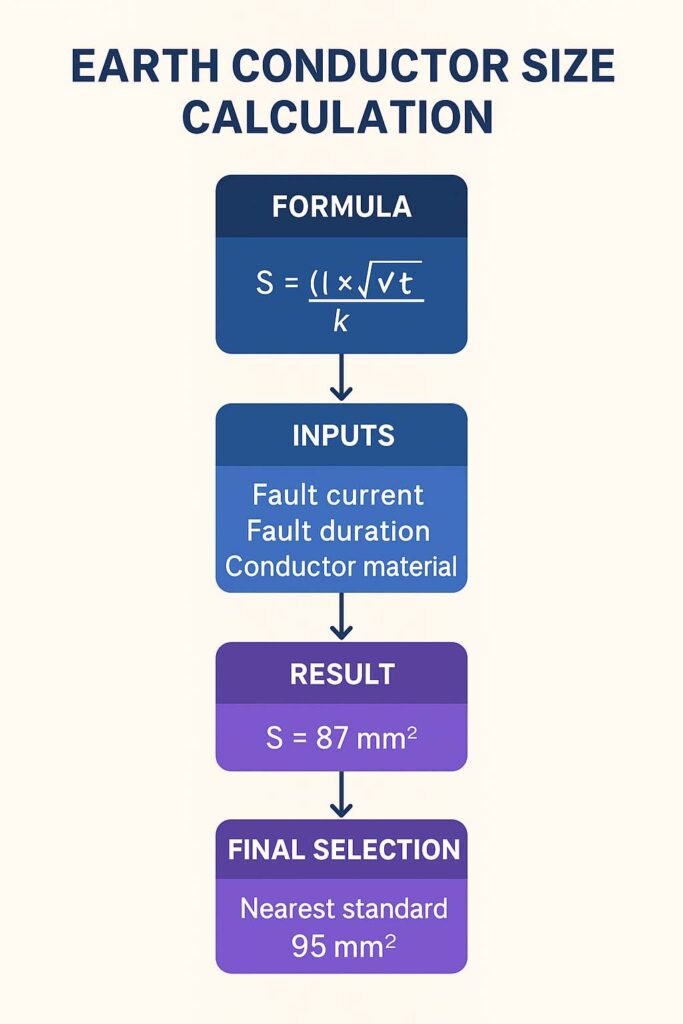
S = (I × √t) / (k)
Where:
- S = Minimum cross-sectional area of the conductor (mm²)
- I = Fault current (A)
- t = Fault duration (seconds)
- k = Constant depending on conductor material and insulation type
The constant k takes into account the conductor’s material (copper or aluminum), its initial temperature, final permissible temperature, and resistivity. For example, copper with PVC insulation has k ≈ 115, while aluminum with PVC insulation has k ≈ 76.
This equation guarantees that the conductor does not exceed its permissible temperature rise during a fault.
Step by Step Earth Conductor Size Calculation
Step 1: Determine Fault Current
The first step is calculating the maximum earth fault current that can flow during a short-circuit condition. This is typically obtained from system fault analysis. For example, if a 400V three-phase system has a prospective fault current of 10 kA, this value will be used for sizing.
Step 2: Identify Fault Duration
Protective devices like circuit breakers or fuses determine how long the fault current will last. Modern protection systems usually clear faults within 0.2 to 1 second. For conservative design, 1 second is often taken unless a faster device is confirmed.
Know more about IEC Standard for DGA Analysis – Complete Technical Guide
Step 3: Select Conductor Material and k-Value
Choose between copper or aluminum, depending on cost and availability. Copper has higher conductivity and allows for smaller conductor sizes compared to aluminum. For copper with PVC insulation, the k value is 115.
Step 4: Apply the Formula
Let’s take an example:
- Fault current (I) = 10,000 A
- Fault duration (t) = 1 second
- Conductor material = Copper, k = 115
S = (10,000 × √1) / 115
S = 87 mm²
So, the minimum earth conductor cross-section should be 87 mm². In practice, the next standard size, 95 mm², is selected.
Step 5: Check with Minimum Standard Requirements
Standards also specify minimum conductor sizes regardless of calculation results. For example, IEC requires:
- 16 mm² for copper if unprotected
- 25 mm² for aluminum if unprotected
If conductors are mechanically protected, smaller sizes may be acceptable.
Step 6: Adjust for Practical Installation
Once the theoretical size is calculated, consider installation conditions. For example, long runs may require larger sizes to reduce resistance. Mechanical protection and redundancy also influence the final choice.

Know more about IEC Standard for Battery Charger – Complete Technical Guide
Table: k Values for Different Materials and Insulations
| Material | Insulation Type | k Value (A·√s/mm²) |
|---|---|---|
| Copper | PVC | 115 |
| Copper | XLPE | 143 |
| Aluminum | PVC | 76 |
| Aluminum | XLPE | 94 |
Example 2: Aluminum Conductor
Let’s calculate for aluminum conductor under the same fault conditions:
- Fault current = 10,000 A
- Fault duration = 1 second
- k = 76
S = (10,000 × √1) / 76
S = 131 mm²
The nearest standard aluminum conductor size is 150 mm².
Simplified Rules for Quick Sizing
While the formula is precise, in practice, electricians often follow simplified rules:
- If phase conductor ≤ 16 mm², earth conductor = same size as phase conductor.
- If phase conductor between 16 mm² and 35 mm², earth conductor = 16 mm².
- If phase conductor > 35 mm², earth conductor = half the phase conductor size.
These rules come from IEC 60364 and are widely used for small to medium installations.
Know more about Best Electrical Design Software for Industrial Projects
Why Fault Duration is Critical
A short-circuit current lasting 0.2 seconds requires a smaller conductor compared to the same current lasting 1 second. This is why protection coordination is vital. If circuit breakers trip faster, conductor sizes can be optimized. If devices are slow, larger conductors are needed to withstand the heating effect.
Comparison Between Copper and Aluminum Earth Conductors
| Property | Copper | Aluminum |
|---|---|---|
| Conductivity | High | Medium |
| Size Requirement | Smaller | Larger |
| Weight | Heavy | Light |
| Cost | Expensive | Cheaper |
| Durability | Better | Prone to corrosion |
This comparison highlights why copper is often preferred for critical installations despite higher costs.
Common Mistakes in Earth Conductor Size Calculation
- Ignoring fault duration and using only phase conductor size.
- Not checking minimum requirements from standards.
- Forgetting to consider installation environment and derating factors.
- Oversizing without justification, leading to unnecessary cost.
Practical Design Example
Suppose we have a three-phase, 415V distribution board with:
- Prospective fault current = 6 kA
- Protection trip time = 0.5 s
- Material = Copper with PVC insulation
Calculation:
S = (6000 × √0.5) / 115
S = (6000 × 0.707) / 115
S = 36.8 mm²
The nearest standard size is 50 mm² copper conductor. This size ensures both safety and compliance.
Use our online tool Power Factor Correction Capacitor Calculator – Complete Technical Guide
Why Standards Must Always Be Followed
Even if calculations show a smaller conductor is sufficient, standards set by IEC, NEC, and IEEE must be followed. These standards ensure safety and legal compliance. Insurance companies and regulatory authorities always check if installations meet the required codes.
Conclusion
Proper earth conductor size calculation is essential for any safe and efficient electrical design. Using the IEC formula with fault current, duration, and k-values ensures accuracy. At the same time, simplified rules and standard requirements provide quick guidance. Whether you use manual calculations or a digital tool like an earthing cable size calculator, the key is to balance safety, cost, and compliance.
In summary, a well-sized earth conductor protects lives, equipment, and property from electrical hazards. Engineers and electricians must always double-check calculations, follow standards, and apply good engineering judgment.
Follow Us on Social:
Subscribe our Newsletter on Electrical Insights for latest updates from Electrical Engineering Hub
#EarthConductorSizeCalculation, #ElectricalEngineering, #EarthingSystem, #GroundingConductor, #ElectricalSafety, #ConductorSizing, #CableSizing, #EarthingCalculation, #ElectricalDesign, #PowerSystem, #ElectricalStandards, #ElectricalProtection, #ElectricalInstallation, #GroundingSystem, #ElectricalGuide


