
Earth Cable Size for Bonding: Complete IEC & NEC Sizing Guide
Choosing the correct Earth Cable Size for Bonding is important for electrical safety, fault-current control, and reliable operation of protective devices. A bonding conductor connects exposed or extraneous conductive parts so that they remain at nearly the same potential during normal operation and, more importantly, during an earth fault.
The required conductor size depends on the type of bonding, installation method, protective conductor size, fault current, disconnection time, and applicable electrical standard. IEC 60364-5-54 and the NEC use different sizing methods, so the installation standard should always be identified before selecting a cable.
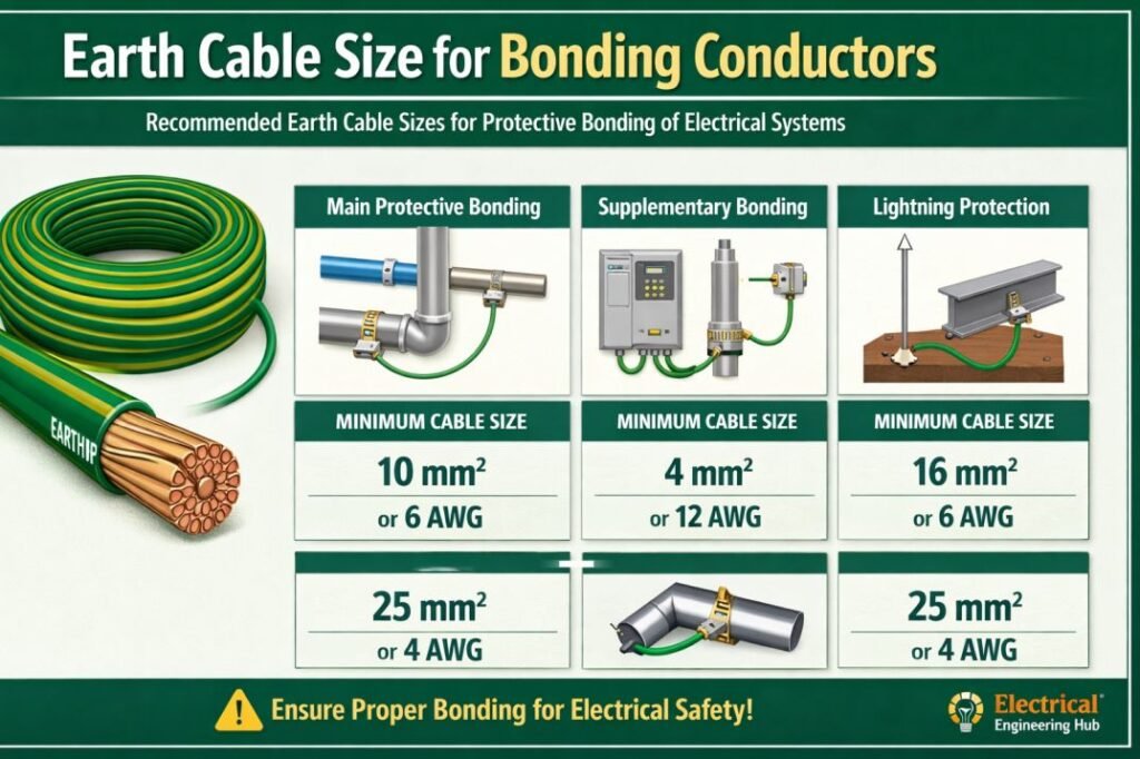
Table of Contents
Table of Contents
Quick Earth Cable Size for Bonding Chart
| Bonding Application | Typical Copper Size | Common Sizing Basis |
|---|---|---|
| Main protective bonding | 6 mm² Cu minimum in many IEC installations | IEC 60364-5-54 |
| Supplementary bonding | 2.5 mm² Cu when mechanically protected | IEC 60364-5-54 |
| Supplementary bonding | 4 mm² Cu when not mechanically protected | IEC 60364-5-54 |
| Equipment bonding conductor | Based on circuit protection | NEC 250.122 |
| Supply-side bonding jumper | Based on largest ungrounded conductor | NEC 250.102(C) |
| Metal enclosure bonding | Based on applicable protective/bonding rules | IEC/NEC |
These are common reference values, not a universal cable-size selection. The actual design must consider the complete installation and governing code.
What Is Bonding in an Electrical System?
Bonding is the intentional electrical connection between conductive parts that could otherwise develop different voltages. These parts can include metal enclosures, structural steel, water pipes, cable trays, equipment frames, and other exposed or extraneous conductive parts.
The purpose is not simply to connect everything to earth. Bonding creates a low-impedance path that helps fault current return to the source and allows the protective device to disconnect the faulty circuit quickly.
For example, if a motor develops an insulation fault and its metal frame becomes energized, the protective bonding path should carry sufficient fault current to operate the fuse, circuit breaker, or other protective device.
This makes bonding an important part of the protective earthing system.
How Is Earth Cable Size for Bonding Determined?
Under IEC-based installations, bonding conductor selection is linked to the protective conductor and the type of bonding being installed. The applicable requirements are found primarily in IEC 60364-5-54.
For supplementary bonding, the conductor is commonly selected in relation to the protective conductor connected to the equipment. Mechanical protection also affects the minimum copper conductor size.
For fault protection, the adiabatic equation may be used:
S = √(I²t) / k
Where:
- S = conductor cross-sectional area in mm²
- I = fault current in amperes
- t = protective device operating time in seconds
- k = material and insulation-dependent constant
This calculation becomes particularly important where prospective fault current is high or disconnection time is relatively long.
IEC Bonding Conductor Size Guide
IEC 60364-5-54 distinguishes between main protective bonding and supplementary bonding. The installation designer should identify the type of conductor before selecting its size.
| Conductor Type | Typical IEC Reference | Common Copper Minimum |
|---|---|---|
| Main protective bonding conductor | IEC 60364-5-54 | 6 mm² Cu |
| Supplementary bonding, mechanically protected | IEC 60364-5-54 | 2.5 mm² Cu |
| Supplementary bonding, not mechanically protected | IEC 60364-5-54 | 4 mm² Cu |
| Protective conductor | IEC 60364-5-54 | Depends on circuit conductor |
| Functional bonding | Project-specific | Engineering calculation |
The minimum values above should not be treated as permission to use the same conductor size in every installation. Large industrial systems, substations, generators, transformers, and high-fault-current equipment may require larger conductors.
For a broader overview of sizing rules, see our guide to Earthing Cable Size Standard for a practical comparison of IEC-based conductor selection requirements.
Main Bonding vs Supplementary Bonding
The terms are sometimes used interchangeably, but they serve different purposes.
Main protective bonding connects extraneous conductive parts to the main earthing terminal or protective earthing system. Examples include metallic water services, structural metalwork, and other conductive services that may introduce a potential into the installation.
Supplementary bonding provides an additional connection between exposed conductive parts and/or extraneous conductive parts. It is often used in locations where maintaining equipotential bonding is especially important.
| Feature | Main Bonding | Supplementary Bonding |
|---|---|---|
| Main purpose | Equipotential bonding | Additional equipotential protection |
| Typical location | Main earthing terminal | Local installation area |
| Typical examples | Water pipe, structural steel | Equipment frames, local metalwork |
| Minimum size | Depends on IEC rules | Depends on protection and installation |
| Design consideration | Largest relevant PE/service conditions | Local protective conductor relationship |
NEC Requirements for Bonding Conductors
Installations designed under the US National Electrical Code follow a different approach.
NEC Article 250 contains requirements for equipment grounding conductors, bonding jumpers, supply-side bonding jumpers, and system bonding connections.
For example, an equipment grounding conductor is generally sized according to the rating of the overcurrent protective device under NEC 250.122.
| Overcurrent Device | Typical Copper Equipment Grounding Conductor |
|---|---|
| 15 A | 14 AWG |
| 20 A | 12 AWG |
| 30 A | 10 AWG |
| 40–60 A | 10 AWG |
| 100 A | 8 AWG |
| 200 A | 6 AWG |
| 300 A | 4 AWG |
| 400 A | 3 AWG |
The NEC tables contain additional values and conditions. If ungrounded conductors are increased in size for voltage drop, the equipment grounding conductor may also need to be increased proportionally under NEC requirements.
Therefore, an IEC calculation should not simply be transferred to a US installation.
Bonding Cable Size for Electrical Panels
Electrical panels require effective bonding between metallic enclosures, doors, covers, gland plates, and other conductive components where applicable.
A bonding jumper may be needed across a hinged panel door if the hinges do not provide a reliable electrical connection.
| Panel Component | Bonding Consideration |
|---|---|
| Metal enclosure | Connect to protective earthing system |
| Hinged metal door | Bond where required |
| Gland plate | Ensure reliable protective connection |
| Cable tray | Bond according to installation design |
| PE bar | Provide secure protective conductor connection |
| Removable cover | Bond where required by design and standard |
The conductor should have secure mechanical connections and suitable corrosion resistance. Paint, powder coating, or oxidation should not prevent a reliable bonding connection where metal-to-metal contact is required.
Factors That Affect Bonding Conductor Selection
Several engineering factors should be checked before finalizing the Earth Cable Size for Bonding.
1. Fault Current
Higher prospective fault current can require a larger conductor. The bonding path must withstand the thermal and mechanical effects of the fault until the protective device operates.
2. Disconnection Time
A fast-acting protective device can reduce the thermal stress on the conductor. A longer fault duration can require a larger cross-sectional area.
3. Conductor Material
Copper and aluminum have different electrical and thermal characteristics. The applicable standard should be used when selecting minimum sizes and correction factors.
4. Mechanical Protection
A conductor installed inside suitable mechanical protection may have a different minimum permissible size than an exposed conductor.
5. Installation Environment
Moisture, chemicals, outdoor exposure, buried installation, and corrosive atmospheres can affect conductor selection and connection methods.
6. Connection Quality
Even a correctly sized bonding cable cannot provide effective protection if its terminals, lugs, clamps, or connection points are loose, corroded, or improperly installed.
Example Bonding Cable Selection
Suppose a small industrial machine has a metal frame that must be connected to the protective earthing system. The installation follows IEC principles and the bonding conductor is mechanically protected.
The designer first identifies whether the conductor is a main protective bonding conductor or a supplementary bonding conductor. If it is supplementary bonding and the applicable minimum is satisfied by 2.5 mm² copper because mechanical protection is provided, that value may be acceptable subject to the complete installation requirements.
For a high-energy industrial system, however, the designer should not rely only on a minimum-size table. Fault current and disconnection time should be checked using the applicable calculation method.
For quick sizing checks across different conductor arrangements, use our earthing conductor size guide, which explains the relationship between protective conductors, bonding conductors, and earthing connections.
Bonding Cable Installation Best Practices
Correct installation is just as important as selecting the conductor size.
- Use appropriately rated copper or aluminum conductors.
- Keep bonding paths short and direct where practical.
- Avoid unnecessary sharp bends.
- Use properly rated lugs, clamps, and terminals.
- Protect conductors from mechanical damage.
- Remove insulating coatings where a direct metal contact is required.
- Protect outdoor connections against corrosion.
- Verify continuity after installation.
- Label protective bonding connections where required.
- Do not use a bonding conductor as a normal current-carrying conductor.
For larger installations, measure and verify the continuity and impedance of the protective path using appropriate test equipment.
Earth Cable Size for Bonding vs Earthing Conductor
Bonding and earthing are closely related but are not identical.
Earthing connects a system or exposed conductive part to the earth or grounding arrangement. Bonding connects conductive parts together to reduce potential differences.
| Term | Main Function |
|---|---|
| Earthing | Provides a connection to earth |
| Protective earthing | Supports fault protection |
| Bonding | Maintains equipotential conditions |
| Main bonding | Connects relevant extraneous conductive parts |
| Supplementary bonding | Adds local protective equipotential connections |
| Equipment grounding | NEC terminology for protective fault-current path |
The distinction matters because each conductor can have different sizing requirements under the governing standard.
If you want to verify a conductor quickly before selecting the final cable, our earth cable size calculator can help compare conductor size requirements using the relevant design inputs.
Common Mistakes When Sizing Bonding Cables
One of the most common mistakes is selecting a bonding conductor based only on the physical size of the equipment. Electrical fault conditions are more important than equipment dimensions.
Other mistakes include:
- Using a minimum table value without checking the applicable standard.
- Ignoring fault current and disconnection time.
- Using undersized bonding jumpers on metal doors or covers.
- Assuming every bonding conductor can be the same size.
- Ignoring mechanical protection requirements.
- Failing to account for corrosion at outdoor connections.
- Confusing protective conductors with functional earthing conductors.
- Applying NEC sizing rules directly to an IEC installation.
A proper design should identify the applicable code first and then confirm the conductor using the relevant tables and calculations.
Frequently Asked Questions
What is the minimum size of a bonding conductor?
For many IEC installations, 6 mm² copper is a commonly referenced minimum for main protective bonding, while supplementary bonding may have lower minimums depending on mechanical protection and the applicable requirements. The exact value must be verified against the installation standard.
Is 4 mm² cable enough for bonding?
A 4 mm² copper conductor can be suitable for some supplementary bonding applications under IEC-based installations, particularly where the applicable minimum for an unprotected supplementary bonding conductor is met. It is not a universal bonding size.
What size earth wire is required for metal equipment?
The required size depends on the applicable standard, protective device, circuit conductor, fault current, and installation method. Under IEC rules, protective conductor sizing can be based on the associated phase conductor or an adiabatic calculation.
Does bonding cable need to be the same size as the earth cable?
Not necessarily. Bonding and protective earthing conductors can have different sizing requirements. The correct size depends on whether the conductor is a main bonding conductor, supplementary bonding conductor, equipment grounding conductor, or another type.
Can a bonding conductor be smaller than the phase conductor?
Yes. Protective and bonding conductors are often smaller than phase conductors because their sizing is based on fault conditions and the applicable standard rather than normal load current. However, minimum sizes and fault withstand requirements must always be satisfied.
Follow Us on Social:
Subscribe our Newsletter on Electrical Insights for latest updates from Azad Circuit Hub
#EarthCableSize, #ElectricalBonding, #IECStandards, #NECCode, #EarthConductor, #GroundingSystem, #ProtectiveConductor, #ElectricalSafety, #CableSizing, #Earthing
