What is Pick Up Voltage in a Over Voltage Relay: Best Guide
In electrical protection systems, relays play a crucial role in preventing damage to equipment caused by abnormal voltage levels. One of the most important parameters in an over voltage relay is the pick up voltage. Understanding what “pick up voltage in a over voltage relay” means, how it is set, and how international standards like IEC define it, is essential for engineers, technicians, and students working in power systems.
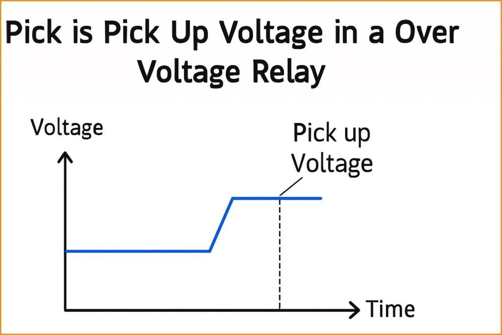
An over voltage relay operates when the system voltage exceeds a predetermined limit. This limit is known as the pick up voltage. When the measured voltage surpasses this threshold, the relay “picks up” or activates, initiating a tripping command to isolate the affected section.
Table of Contents
Table of Contents

In simple terms, pick up voltage in a over voltage relay is the voltage level at which the relay starts responding to an overvoltage condition. Below this level, the relay remains idle and does not issue any trip signal. Once this limit is reached, the relay coil gets energized and begins its operation sequence, often with a small time delay to avoid nuisance tripping due to transient surges.
Key Takeaways
- Pick up voltage in a over voltage relay is the minimum voltage level at which the relay begins to operate.
- It ensures the relay only trips during sustained overvoltage conditions.
- IEC standards define allowable settings for pick up voltage to ensure accuracy and reliability.
- Proper adjustment of pick up voltage is critical for system stability and protection coordination.
- Common settings range from 105% to 130% of nominal voltage, depending on the system and relay type.
Know more about Industrial Control Transformer Manufacturers in China: Best Guide
Understanding Pick Up Voltage in a Over Voltage Relay
The concept of pick up voltage in a over voltage relay is fundamental in power system protection. In electrical networks, small voltage fluctuations are common due to load variations. Protection relays must ignore normal fluctuations and respond only to dangerous overvoltage levels. The pick up voltage defines that precise boundary between normal and abnormal conditions.
When voltage remains below the pick up level, the relay’s electromagnetic element or digital sensing circuit does not respond. Once the voltage crosses the pick up point, the relay’s internal mechanism becomes active. The actual tripping, however, may still depend on time delay or coordination with other relays.
For example, if the system nominal voltage is 400 V, and the relay pick up voltage is set at 110%, the relay will start operating when the voltage exceeds 440 V. If this condition persists for a set time (say, 1 second), the relay trips the circuit breaker to disconnect the load.
Importance of Pick Up Voltage Setting
The pick up voltage must be carefully chosen. If it is set too low, the relay may trip unnecessarily during harmless voltage fluctuations. If it is set too high, the relay might fail to protect the system during dangerous overvoltages.
Correct setting ensures:
- Selective protection — only the faulty section is isolated.
- System stability — the rest of the network remains unaffected.
- Equipment safety — insulation and devices remain protected from voltage stress.
- Reduced false trips — transient spikes do not cause interruptions.
The right pick up voltage helps maintain balance between sensitivity and stability in the protection scheme.
Know more about Top 12 Current Transformer Manufacturers in Australia
Example of Pick Up Voltage Calculation
Let’s consider a simple case.
| Parameter | Symbol | Value |
|---|---|---|
| Nominal Voltage | V_n | 11 kV |
| Pick Up Setting | K_p | 1.10 (110%) |
| Pick Up Voltage | V_pickup | V_n x K_p = 11 x 1.10 = 12.1 kV |
So, in this case, the relay will start to operate when the system voltage exceeds 12.1 kV. This example illustrates how easily the pick up voltage can be determined using a multiplication factor based on nominal voltage.
IEC Standards for Pick Up Voltage in Over Voltage Relays
The International Electrotechnical Commission (IEC) provides standardized guidelines to ensure uniformity and safety across different protection devices. The most relevant standard for voltage relays is IEC 60255, which specifies performance and testing requirements for protection relays.
According to IEC 60255-127 (Measuring relays and protection equipment – Part 127: Functional requirements for over/under voltage protection):
- The pick up voltage (often referred to as the operating threshold) should be expressed as a percentage of the nominal system voltage.
- Common operating range is 105% to 130% of nominal voltage for over voltage relays.
- The reset ratio, which defines the point at which the relay returns to its normal state, is typically between 95% and 99% of pick up voltage.
- The standard allows ±3% tolerance on the pick up voltage setting to accommodate manufacturing and calibration variations.
Example Based on IEC 60255
| System Nominal Voltage | Pick Up Setting Range | Reset Voltage Range | Tolerance |
|---|---|---|---|
| 400 V | 420 V – 520 V (105–130%) | 400 V – 515 V | ±3% |
| 11 kV | 11.55 kV – 14.3 kV (105–130%) | 11.0 kV – 14.0 kV | ±3% |
This table shows that relay manufacturers provide adjustable ranges to meet system protection requirements under IEC standards.
Know more about High Voltage Transformer Testing Procedure
Behavior of Relay During Pick Up
The operation sequence of an over voltage relay can be visualized in three phases:
- Normal Condition – Voltage remains below pick up value. The relay is inactive.
- Pick Up Phase – Voltage exceeds pick up level. The relay coil energizes but may wait for a time delay.
- Tripping Phase – If the overvoltage continues beyond the delay setting, the relay sends a trip command.
For example, a relay with a pick up voltage of 440 V and a time delay of 0.5 seconds will start its timer as soon as voltage exceeds 440 V. If voltage drops below 440 V before 0.5 seconds, the relay resets. Otherwise, it trips the circuit breaker after 0.5 seconds.
This ensures protection against sustained overvoltages but immunity against short spikes.
Digital and Numerical Relays Pick Up Setting
Modern numerical relays provide highly accurate pick up voltage adjustments through digital settings. Engineers can set exact values (for example, 1.08 × Vn or 1.15 × Vn) via configuration software.
Digital relays also feature programmable logic to coordinate with under-voltage, frequency, or differential protection. They follow the same IEC guidelines but allow more flexibility and monitoring options.
For instance, in Siemens 7SJ series or ABB REF615, pick up voltage can be set in increments as small as 1 V or 0.1%, ensuring precise control. These relays also log the number of pick up events, helping in trend analysis and reliability assessment.
Factors Affecting Pick Up Voltage Accuracy
Even though modern relays are precise, several factors can influence the accuracy of pick up voltage in a over voltage relay:
- Temperature drift – affects electronic components.
- Supply frequency – small frequency variations can shift pick up point.
- Calibration errors – due to manufacturing or field adjustments.
- Harmonic distortion – may cause false detection of overvoltage.
That’s why IEC requires type tests and routine tests to verify relay performance under various conditions.
Know more about Static Excitation Systems Manufactured in US
Practical Considerations for Setting Pick Up Voltage
When setting pick up voltage in an over voltage relay:
- Check nominal system voltage and maximum allowable operating voltage.
- Consider system insulation coordination – the relay must trip before insulation breakdown.
- Ensure selectivity – coordination with other voltage or differential relays.
- Verify reset margin – typically 3–5% below pick up voltage.
Example Practical Setting
For a 132 kV transmission line:
- Nominal voltage = 132 kV
- Maximum continuous = 138 kV
- Pick up = 1.10 × 132 = 145.2 kV
- Reset = 0.97 × 145.2 = 140.8 kV
This ensures tripping occurs only when voltage is dangerously high, protecting transformers and insulation.
Applications of Over Voltage Relays
Over voltage relays are widely used in:
- Transmission and distribution substations
- Generator protection
- Motor control centers
- Industrial and renewable energy systems
In solar and wind plants, where grid voltage can fluctuate, proper pick up voltage settings prevent inverter damage and ensure compliance with grid codes.
Why IEC Standards Matter
IEC standards bring uniformity, reliability, and safety. By following IEC 60255, utilities ensure that relays from different manufacturers operate consistently. This simplifies protection coordination and reduces system risk.
Relays designed as per IEC requirements also ensure compatibility with grid interconnection codes and national standards like IEEE C37 and EN 60255.
Know more about Power Factor Correction Capacitor Calculator – Complete Technical Guide
Final Thoughts
The pick up voltage in a over voltage relay is a vital parameter defining when the relay will respond to abnormal conditions. Setting it correctly ensures equipment protection without unnecessary tripping. Engineers must follow IEC 60255 guidelines and validate settings through testing and coordination studies.
An accurate pick up voltage ensures that the relay performs its intended role — safeguarding the power system, preventing equipment damage, and maintaining operational stability.
Ultimately, a well-configured over voltage relay not only enhances reliability but also extends the life of critical assets in electrical networks.
Follow Us on Social:
Subscribe our Newsletter on Electrical Insights for latest updates from Electrical Engineering Hub
#OverVoltageRelay, #PickUpVoltage, #RelayProtection, #ElectricalEngineering, #PowerSystemProtection, #VoltageRelay, #IECStandards, #RelaySettings, #TransformerProtection, #ElectricalSafety, #ProtectionRelay, #ControlSystems, #VoltageMonitoring, #IndustrialAutomation, #ElectricalDesign


