
Cable Size for Motor Calculator | IEC 60364 & NEC 430 | Single & 3-Phase
Selecting the correct cable for a motor is one of the most important steps in designing a safe and efficient electrical installation. A cable that is too small can overheat, create excessive voltage drop, and reduce motor performance, while an oversized cable unnecessarily increases project cost. A reliable cable size for motor calculator simplifies this process by considering the key installation factors required by international standards.
Whether you are an electrical engineer, contractor, technician, or engineering student, this tool helps determine an appropriate motor cable size based on IEC 60364 and NEC 430 recommendations. Simply enter the required motor and installation details, and the calculator provides a practical cable size recommendation.
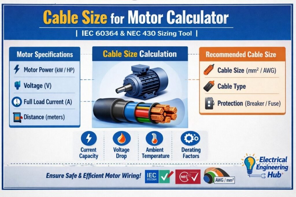
Table of Contents
Table of Contents
Looking for a general kW to cable size calculator?
Use the tool here == > KW to Cable Size Calculator
Cable Size for Motor Calculator
Motor Circuit Design Reference
Cable Size for Motor Calculator
Work out the minimum conductor size for a motor branch circuit under IEC 60364 or NEC 430, covering full-load current, ambient and grouping derating, and voltage drop, for single-phase or three-phase supplies.
01
Motor and supply
Nameplate rating and supply conditions used to derive the full-load current.
02
Cable and installation
Conductor material, insulation and the conditions the cable will actually run in.
03
Cable run and voltage drop limit
Route length from starter or protective device to the motor terminals, and the maximum drop you will accept.
Result
Recommended conductor
Reflects the values entered on the left.
Enter your motor and installation details, then press Calculate cable size.
How to use this calculator
- Choose the design standard, IEC 60364 or NEC 430, and the supply type, single-phase or three-phase.
- Enter the motor rating, supply voltage, power factor and efficiency from the nameplate or datasheet.
- Set the conductor material, insulation rating, ambient temperature and how many other loaded circuits run alongside this cable.
- Enter the one-way cable length and the maximum voltage drop you are prepared to accept.
- Press Calculate cable size. The result panel shows the full-load current, the derated ampacity requirement, the recommended size, and whether ampacity and voltage drop both pass.
- If a field is changed afterward, press Calculate again to refresh the result, or use the live update as a quick preview.
What this tool is checking
The calculator starts from the motor’s full-load current, then checks two separate things against the cable you would actually buy: whether it can carry that current continuously once ambient heat and the effect of nearby loaded cables are taken into account, and whether the cable is short and thick enough that the motor still receives an adequate voltage at its terminals over the length of the run.
Whichever of those two checks needs the larger conductor is the one that decides the final recommended size, and the result panel tells you which of the two was the limiting factor.
Assumptions built into the result
Ampacity values are reference figures for a single circuit installed by a common clipped or tray-mounted method, at the standard base ambient used by each standard. Your actual installation method, cable bunching, burial depth or conduit fill can change the real allowable current, so treat a marginal pass or fail as a reason to check the full reference table rather than a final answer.
Aluminium and higher-temperature insulation figures are derived using standard industry adjustment ratios rather than a full separate table, which is accurate enough for preliminary sizing but should be confirmed against the manufacturer’s cable data for a final design.
Find more Electrical Engineering Tools for easy electrical calculations and estimations.
What Is a Motor Cable Size Calculator?
A motor cable size calculator is an engineering tool that determines the correct cable cross-sectional area for supplying electric motors safely and efficiently. It supports both single-phase and three-phase motors by calculating the motor current first and then recommending a suitable cable size based on electrical standards, installation conditions, and allowable voltage drop.
Since the current calculation differs for single-phase and three-phase systems, the calculator automatically applies the appropriate formula before selecting the cable.
| Motor Type | Current Calculation Basis |
|---|---|
| Single-Phase Motor | Uses voltage, power, power factor, and efficiency |
| Three-Phase Motor | Uses line voltage, power, power factor, efficiency, and √3 factor |
Using a Cable Size for Motor Calculator helps reduce overheating, excessive voltage drop, and energy losses while ensuring compliance with IEC 60364 and NEC 430 requirements.
It is especially useful for electricians, panel builders, engineers, and contractors who need quick, accurate motor cable sizing for new installations or upgrades.
Need to calculate cable size for applications beyond motors? Explore our complete Cable Size Calculator to size cables for residential, commercial, industrial, DC, and solar installations using IEC, NEC, and BS 7671 guidelines.
How to Use the Calculator
Using the cable size for motor calculator requires only a few basic motor and installation details.
- Enter the motor power in kW or HP.
- Select single-phase or three-phase supply.
- Choose the operating voltage.
- Enter the cable length.
- Select copper or aluminium conductor.
- Specify installation conditions such as ambient temperature and cable grouping.
- Select the applicable design standard (IEC 60364 or NEC 430).
- Review the recommended cable size and voltage drop results.
Before purchasing cables, always compare the calculated result with local regulations and manufacturer recommendations. In industrial installations, engineers may also consider future load expansion when selecting conductor sizes.
Motor Cable Sizing Formula: Single-Phase vs. Three-Phase
Selecting the correct cable begins by calculating the motor's full-load current. The Cable Size for Motor Calculator uses different current formulas for single-phase and three-phase motors before applying voltage drop, installation conditions, and ampacity requirements. Single phase motor wire size follows below formula.
Single-Phase Current Formula
For a single phase motor wire size:
I = P / (V × PF × η)
Where:
| Symbol | Meaning |
|---|---|
| I | Current (A) |
| P | Motor power (W) |
| V | Supply voltage (V) |
| PF | Power factor |
| η | Motor efficiency |
Example: A 2.2 kW motor operating at 230 V with PF = 0.85 and efficiency = 90% draws:
I = 2200 ÷ (230 × 0.85 × 0.90) ≈ 12.5 A
Three-Phase Current Formula
For a three-phase motor:
I = P / (√3 × V × PF × η)
Example: A 7.5 kW motor supplied at 415 V with PF = 0.85 and efficiency = 92% draws approximately 13.5 A. This calculated current is then used to determine the minimum cable size while considering derating factors, installation method, and allowable voltage drop according to IEC 60364 or NEC 430.
Why Cable Size Matters for Motors
Motor circuits place different demands on cables compared to ordinary lighting or power circuits. Electric motors draw high starting currents and often operate continuously for extended periods. Because of this, selecting the proper cable size directly affects safety, efficiency, and equipment life.
Using an undersized cable may result in:
- Excessive conductor heating
- Insulation deterioration
- Frequent overload relay tripping
- Reduced motor starting torque
- Increased energy losses
- Premature motor failure
Voltage drop is another major concern. When excessive voltage is lost along the cable, the motor must draw additional current to produce the required torque. This increases winding temperature and reduces operating efficiency.
Choosing the correct conductor size also helps ensure compliance with national electrical codes while minimizing maintenance costs over the lifetime of the installation.
IEC vs NEC Cable Sizing — What's the Difference
Both IEC 60364 and NEC 430 provide guidance for motor circuit design, but they approach cable selection differently.
| Feature | IEC 60364 | NEC 430 |
|---|---|---|
| Primary Basis | Current-carrying capacity with correction factors | Full-load current tables and code requirements |
| Voltage Drop | Recommended design consideration | Recommended for efficient motor operation |
| Correction Factors | Extensive ambient and grouping adjustments | Ampacity adjustment factors |
| Motor Protection | Coordinated with overload devices | Detailed motor branch circuit rules |
| Global Use | Europe, Asia, Middle East, Africa | United States and some international projects |
The calculator supports both approaches, allowing engineers working on international projects to compare recommendations without performing separate calculations.
Motor circuits are just one part of electrical design. Use our comprehensive Cable Size Calculator to determine the correct conductor size for any load, voltage, installation method, and cable length with greater accuracy.
Minimum THWN-2 Copper Conductor for a 10 HP, 208V, 3-Phase Motor
For a 10-horsepower, 208-volt, 3-phase continuous-duty motor with a 27.6 A nameplate current, the conductor is sized using the NEC motor-circuit rules rather than simply matching the nameplate amperage. Under NEC 430.6(A)(1), motor branch-circuit conductors are generally based on the applicable table full-load current; for a 10 HP, 208V, 3-phase motor, NEC Table 430.250 gives 30.8 A. Applying 125% for continuous motor duty under NEC 430.22, the minimum ampacity is 38.5 A.
| Calculation | Value |
|---|---|
| Motor rating | 10 HP |
| Voltage / phase | 208 V / 3-phase |
| Nameplate current | 27.6 A |
| NEC Table 430.250 FLC | 30.8 A |
| Conductor sizing | 30.8 × 125% = 38.5 A |
| Minimum THWN-2 copper | #8 AWG |
| Typical #8 Cu ampacity | 50 A at 75°C |
Therefore, #8 AWG THWN-2 copper is the minimum conductor size under the stated assumptions. Use the motor cable size calculator to verify voltage drop, installation conditions, and any applicable adjustment or correction factors before final selection.
Factors That Affect Motor Cable Size
Several installation variables influence the final cable selection. Ignoring any of these factors can produce inaccurate sizing results.
Ambient Temperature
Cable ampacity decreases as surrounding temperature rises. Higher temperatures reduce the cable's ability to dissipate heat, requiring larger conductors to carry the same current safely.
Industrial plants, rooftops, and outdoor installations often require temperature correction factors before selecting the final cable size.
Grouping/Number of Circuits
When multiple cables are installed together in trays, conduits, or ducts, heat builds up between adjacent conductors.
Grouping correction factors reduce allowable current capacity, which may require selecting a larger conductor than would be needed for a single cable installation.
Conductor Material
Copper and aluminium conductors have different electrical characteristics.
| Property | Copper | Aluminium |
|---|---|---|
| Conductivity | Higher | Lower |
| Cable Size Required | Smaller | Larger |
| Weight | Heavier | Lighter |
| Initial Cost | Higher | Lower |
| Mechanical Strength | Better | Moderate |
Because aluminium has lower conductivity, it generally requires a larger cross-sectional area to carry the same current as copper.
Cable Length and Voltage Drop
Long cable runs increase conductor resistance and cause voltage loss between the supply source and the motor.
A voltage drop calculator motor function helps verify that the selected conductor maintains acceptable voltage at the motor terminals. If voltage drop exceeds recommended limits, the conductor size should be increased.
This is particularly important for pumps, compressors, conveyor systems, and agricultural motors located far from the electrical distribution panel.
Starting Method and Cable Sizing
A motor's starting method directly affects the inrush current and can influence cable selection. With a Direct-On-Line (DOL) starter, the motor typically draws 6–8 times its full-load current during startup. Although the Cable Size for Motor Calculator is based on continuous load current, the cable must also withstand the short-duration starting current without excessive voltage drop or overheating. Know more about motor cable sizing in our detailed guide which covers the starting current and running.
Star-delta starters reduce the starting current to approximately one-third of DOL values, while soft starters and Variable Frequency Drives (VFDs) provide smoother acceleration with lower current peaks.
| Starting Method | Typical Starting Current | Cable Sizing Consideration |
|---|---|---|
| DOL Starter | 6–8 × FLC | Check voltage drop during starting |
| Star-Delta Starter | 2–3 × FLC | Lower starting current may reduce voltage drop |
| Soft Starter / VFD | 1.5–3 × FLC | Smooth starting with reduced electrical stress |
For a detailed comparison and dedicated calculations for star-delta systems, see our Star Delta Motor Cable Size Calculator guide.
Standard Motor Cable Size for Single Phase & Three Phase
The following reference table provides typical cable sizes for common motor ratings. These values are intended as a quick guide and should be verified using the Cable Size for Motor Calculator, considering installation method, ambient temperature, voltage drop, cable type, and applicable IEC 60364 or NEC 430 requirements.
| Motor Rating | Single-Phase Cable Size | Three-Phase Cable Size |
|---|---|---|
| 1 HP (0.75 kW) | 2.5 mm² | 1.5 mm² |
| 2 HP (1.5 kW) | 4 mm² | 2.5 mm² |
| 5 HP (3.7 kW) | 6 mm² | 4 mm² |
| 10 HP (7.5 kW) | 10 mm² | 6 mm² |
| 20 HP (15 kW) | 16 mm² | 10 mm² |
| 30 HP (22 kW) | 25 mm² | 16 mm² |
| 50 HP (37 kW) | 35 mm² | 25 mm² |
These cable sizes represent common industry practice for copper conductors under normal conditions.
Standard Motor Wire Size Chart against HP/kW
Use this quick reference with the Cable Size for Motor Calculator to estimate typical copper cable sizes for common three-phase motors. Always verify the final selection based on installation method, ambient temperature, voltage drop, and applicable IEC 60364 or NEC 430 requirements.
| Motor Rating | Approx. Full Load Current (A) | Typical Copper Cable Size |
|---|---|---|
| 5 HP (3.7 kW) | 7–8 A | 2.5 mm² |
| 7.5 HP (5.5 kW) | 11–12 A | 4 mm² |
| 11 kW (15 HP) | 21–22 A | 6 mm² |
| 15 kW (20 HP) | 28–30 A | 10 mm² |
| 20 kW (27 HP) | 37–39 A | 10 mm² |
| 30 kW (40 HP) | 56–60 A | 16 mm² |
| 40 kW (54 HP) | 74–78 A | 25 mm² |
Reference values only. Confirm cable sizing using actual motor full-load current and installation conditions.
Common Mistakes in Motor Cable Sizing
Even when using a Cable Size for Motor Calculator, incorrect inputs or assumptions can result in undersized or oversized cables. One of the most common mistakes is selecting a cable based only on the motor's full-load current while ignoring voltage drop, especially for long cable runs.
Looking for a quicker way to size electrical cables? Try our Cable Size Calculator to perform accurate calculations for single-phase and three-phase circuits while following BS 7671 and international wiring standards.
Another frequent error is overlooking derating factors such as high ambient temperature, grouped cables, or installation methods, which reduce the cable's current-carrying capacity. Many installers also forget that motor starting current can affect cable performance and protective device coordination. Finally, choosing a cable without considering future load expansion may lead to costly replacements.
| Mistake | Possible Result |
|---|---|
| Ignoring voltage drop | Low motor voltage and poor performance |
| Skipping derating factors | Cable overheating |
| Using only FLC for sizing | Incorrect cable selection |
| Ignoring starting current | Tripping and startup issues |
| No allowance for future expansion | Early cable replacement |
Always verify the calculator results against IEC 60364 or NEC 430 requirements before finalizing the cable size.
Looking for a universal cable sizing tool? Visit our Cable Size Calculator hub to access calculators, sizing charts, voltage drop tools, and code-based guidance for a wide range of electrical applications.
Frequently Asked Questions
What size cable do I need for a 15 kW motor?
The required cable depends on supply voltage, installation method, cable length, ambient temperature, and conductor material. A cable size for motor calculator provides a more accurate recommendation than selecting a cable based solely on motor power.
Does cable size depend on motor starting method?
Yes. Direct-On-Line starting produces higher starting current than soft starters or variable frequency drives. Higher starting current can increase voltage drop, influencing the required conductor size.
What voltage drop is acceptable for motor circuits?
Many designers aim to keep voltage drop within approximately 5% under normal operating conditions, although local regulations and project specifications should always take precedence.
Copper vs aluminium — does it change the cable size?
Yes. Aluminium has lower conductivity than copper, so a larger conductor is usually required to carry the same current while maintaining similar voltage drop performance.
Can the same cable size be used for every motor with the same power rating?
No. Two motors with identical power ratings may require different cable sizes because installation conditions, cable length, ambient temperature, starting method, and applicable electrical standards can all affect the final selection.
What is the cable size formula for a single-phase motor?
For a single phase motor wire size, current is calculated as I = P / (V × PF × η). After finding the current, select a cable based on ampacity, voltage drop, and installation conditions. Always verify the final size against IEC or NEC requirements.
What is the cable size formula for a three-phase motor?
For a three-phase motor, use I = P / (√3 × V × PF × η) to calculate the full-load current. Choose a cable that can safely carry this current while meeting voltage drop and derating limits. Standard cable sizing tables should then be applied.
Does starting method (DOL vs. star-delta) affect cable size?
Yes. A DOL starter draws a much higher starting current than a star-delta starter, but cable size is generally based on the motor's full-load current and voltage drop. In some cases, frequent starts or long cable runs may require a larger cable.
How do I account for voltage drop in motor cable sizing?
Calculate the expected voltage drop using the cable length, load current, conductor resistance, and power factor. If the voltage drop exceeds the recommended limit (typically 3–5%), increase the cable size. This ensures efficient motor operation and reliable starting performance.
How thick is the wire used for a three-phase 5-kilowatt motor?
A 5 kW three-phase motor typically requires a cable between 2.5 mm² and 4 mm² copper, depending on voltage, installation method, cable length, and allowable voltage drop. The exact size should be determined using IEC 60364 or NEC 430 guidelines. Always verify the motor's full-load current before selecting the cable.
What cable size is required for a 2.2 kW three-phase motor?
For a typical 400 V three-phase motor, 2.5 mm² copper cable is commonly suitable, subject to installation conditions, voltage drop, and applicable electrical standards.
What cable size is required for a 16 kW, 220 V, 60 Hz load located 150 meters from the supply?
For a 220 V single-phase 16 kW load, the current is about 72.7 A; at 150 m, voltage drop becomes the key factor. A 35 mm² copper cable is a practical starting point, but the final size should be verified for installation method, allowable voltage drop, temperature, and whether the load is continuous.
Can 2.5 sq mm aluminium wire run a 1 HP motor?
Yes, a 2.5 mm² aluminium cable can generally supply a 1 HP motor, provided the installation method, cable length, voltage drop, and motor starting current are suitable. For reliable operation, verify the cable ampacity and voltage drop before installation.
What size wire is needed to feed two separate 7.5 HP, 480V, 3-phase motor circuits in a single conduit?
Using NEC motor FLC of 11A per motor, each circuit requires a minimum 14 AWG copper conductor at 125% FLC (13.75A). For two circuits in one conduit, 14 AWG copper THHN/THWN-2 remains adequate for ampacity, subject to conduit fill, adjustment factors, voltage drop, and applicable NEC requirements.
Can a 1 HP motor run on a 2.5 mm² cable?
Yes, a 2.5 mm² copper cable can generally supply a 1 HP motor, provided the voltage, installation method, cable length, and motor starting current are suitable.
For a typical 230 V single-phase 1 HP motor, 2.5 mm² copper is usually adequate, but proper breaker, overload protection, and voltage-drop checks are still required.
What cable size is required for a 3 HP, 480 V, 1800 RPM motor according to the CEC?
For a typical 3-phase 3 HP, 480 V motor, the CEC motor full-load current is about 4.8 A, so 14 AWG copper is generally sufficient for the branch-circuit conductors. Size the final conductor and protection according to CEC motor rules, including allowable ampacity, installation conditions, and voltage drop.
What is the minimum size RHW-2 copper conductor required for a 200-horsepower, 575-volts, 3-phase motor that is continuous duty with a nameplate current of 182.9 amperes?
Under NEC motor-sizing rules, the conductor ampacity must be at least 125% of the motor current: 182.9 × 1.25 = 228.6 A. Therefore, 4/0 AWG copper RHW-2 is the minimum size, subject to applicable NEC ampacity and installation conditions.
What is the minimum-size THWN copper conductor required for a 2-horsepower, 115-volt, single-phase, continuous-duty motor with a 22.1-ampere nameplate current?
The minimum conductor size is 10 AWG copper THWN, based on 125% of the motor nameplate current (27.6 A) and the applicable NEC ampacity requirements.
This assumes standard installation conditions with no additional derating factors; verify the final sizing against NEC 430.22 and Table 310.16.
What cable size is required for a 15 kW 3-phase motor?
For a typical 15 kW (20 HP) 3-phase motor, a 6 mm² copper cable is commonly suitable for short-to-moderate runs, subject to installation method and voltage. For longer runs or high ambient temperatures, 10 mm² copper may be preferable to limit voltage drop. Further Use our 3phase 15 kw motor cable size calculator online above.
How to select the correct insulation type and cable size for a three-phase electric motor?
Select the cable insulation type based on the installation environment, voltage, temperature, and applicable code, then size the conductor according to the motor full-load current, voltage drop, ambient temperature, and installation conditions. For motor circuits, also consider the required ampacity and overcurrent protection under the applicable NEC or IEC requirements.
What is the cable size for a 200 HP motor pump?
For a typical 200 HP, 415 V, 3-phase motor, a 95 mm² copper cable may be suitable, but the final size depends on motor full-load current, installation method, voltage drop, ambient temperature, and derating factors. For long runs or demanding conditions, 120 mm² or larger may be required.
What size wire is required for a 600 HP compressor motor at 480 volts with parallel runs?
For a 600 HP, 480V three-phase motor, conductor sizing depends on the motor nameplate FLA, NEC 430 requirements, and the number of parallel runs. As a preliminary guide, multiple parallel copper conductors such as 4/0 AWG or larger per phase may be required, but the exact size must be calculated from the motor FLA and installation conditions.
Can a 10mm² × 3-core cable cater for an 18 kW motor?
Yes, a 10mm² × 3-core copper cable can generally supply an 18 kW three-phase motor, provided the motor voltage, installation method, cable length, ambient temperature, and voltage drop are suitable. For a typical 400 V motor, the running current is around 32–35 A, but final cable sizing should include applicable derating and starting-current considerations.
What gauge wire should I use for a 1.5 HP, 115 V motor running at 15 feet?
For a 1.5 HP, 115 V motor, 12 AWG copper wire is a suitable choice for a 15-foot run, assuming typical installation conditions. Use a properly sized motor circuit breaker and follow NEC requirements for motor branch circuits and starting current.
What size cable would you need for a 600 kW motor working on a 400 V 3-phase supply?
For a 600 kW, 400 V, 3-phase motor, the full-load current can be around 1,000–1,100 A, depending on efficiency and power factor. A suitable installation may require multiple parallel copper cables, with the final size selected based on NEC/IEC ampacity, installation method, voltage drop, and starting current.
What is the typical cable size for a 10 kW, 415 V, 3-phase motor?
A 4 mm² copper cable is typically suitable for a 10 kW, 415 V, 3-phase motor, depending on installation conditions. The final size should be verified for motor FLC, voltage drop, ambient temperature, cable length, and applicable standards.
What size MCB do I need for a 7.5 HP, 400-volt, 3-phase motor powering a fan?
For a 7.5 HP (5.5 kW), 400 V, 3-phase motor, a 16–20 A 3-pole MCB is typically suitable, depending on the motor’s nameplate current and starting method.
Use a motor-rated protective device and set the overload protection according to the manufacturer’s nameplate current; final sizing should account for starting current and local electrical code.
Can a 10 AWG wire single-phase supply a 9 kW motor?
A 10 AWG wire is generally not suitable for a 9 kW single-phase motor because the motor can draw high running and starting current. The required conductor size depends on voltage, motor nameplate current, insulation, installation method, and NEC requirements.
What wire size is needed for a 15 HP, 230-volt, single-phase motor?
For a 15 HP, 230 V single-phase motor, the typical full-load current is about 70 A, so #3 AWG copper is commonly suitable, subject to the motor nameplate current, installation conditions, and applicable NEC requirements.
Can I use a 2.5 mm² cable for star-delta connection for an 18.5 kW motor?
Yes, 2.5 mm² copper cable may be suitable for the motor’s star-delta control circuit, but it is generally not appropriate to size the motor power cables solely at 2.5 mm². The power conductor size must be selected based on motor current, installation method, voltage drop, temperature, and applicable NEC/IEC requirements.
What are the specifications of the D300/150W, 1400 RPM cooling fan motor?
The D300 cooling fan motor is rated at 150 watts with a speed of 1,400 RPM. For the correct voltage, current, capacitor, and wiring details, check the motor nameplate or manufacturer specifications.
What cable size is required for a 30 kW pump motor?
For a typical 30 kW, 3-phase motor, a 10 mm² copper cable is commonly suitable, but the final size depends on voltage, installation method, cable length, ambient temperature, and voltage drop. For long runs or higher derating conditions, 16 mm² may be required.
What cable size is suitable for a 1 HP motor with a 2.1 FLA rating?
For a 1 HP motor drawing 2.1 A FLA, a 2.5 mm² copper cable is generally suitable for typical installations. The final size should also consider cable length, voltage drop, installation method, starting current, and applicable electrical codes.
What is the minimum size RHW-2 copper conductor required for a 5-horsepower, 230-volts, 3-phase Design B motor that is continuous duty with a nameplate current of 13.6 amperes?
Using NEC motor-sizing requirements, the minimum conductor ampacity is 125% of the motor full-load current: 13.6 × 1.25 = 17 A.
Therefore, No. 12 AWG RHW-2 copper is the minimum practical conductor size, provided its allowable ampacity and installation conditions meet the applicable NEC requirements.
What cable size should be used for a 0.75 kW motor?
For a typical 0.75 kW motor, a 1.5 mm² copper cable is generally suitable for normal installations. The final size should be verified based on motor current, cable length, installation method, voltage drop, and applicable electrical standards.
What cable size is needed for a 100 HP motor?
For a typical 100 HP, 3-phase motor, a 35 mm² copper cable may be suitable for many installations, but the final size depends on voltage, motor full-load current, cable length, installation method, ambient temperature, and voltage drop. Always verify sizing using the motor nameplate current and applicable electrical code.
¿Qué calibre de cable se recomienda para alimentar un motor de 2.2 kW a 460 VCA?
Para un motor trifásico de 2.2 kW (≈3 HP) a 460 VCA, normalmente se recomienda cobre de 2.5 mm² (≈14 AWG), sujeto a la corriente de placa, método de instalación y normativa aplicable.
What size cable for a 1.6 kW, 12-volt motor?
A 1.6 kW, 12 V motor draws about 133 A at full load, so a 35 mm² copper cable is a reasonable starting point for short runs. For longer distances, increase the cable size to limit voltage drop; motor starting current should also be considered.
Can a DFT be used to run a 5 kV motor?
A DFT (Drive/variable-frequency drive, depending on the specific equipment) can run a 5 kV medium-voltage motor only if it is specifically designed and rated for 5 kV operation. A standard low-voltage VFD cannot be directly connected to a 5 kV motor; use a properly rated medium-voltage drive system.
What’s the maximum extension cord length for a 1.5 HP motor running on 110 VAC, 60 Hz, 1-phase?
For a typical 1.5 HP motor, keep the extension cord to 50 ft (15 m) or less and use at least 12 AWG copper to limit voltage drop. For longer runs, 10 AWG may be needed depending on motor nameplate current, starting current, and allowable voltage drop.
Will 10 mm² 3-phase cable handle a 2.2 kW motor, an additional 4 kW motor, a 32 A commando socket, and a single-phase subboard over a 100 m run?
A 10 mm² 3-phase cable may carry the combined load, but voltage drop at 100 m and the 32 A socket load must be checked; a larger cable may be required depending on installation method and supply voltage. For a definitive size, calculate the maximum demand, voltage drop, starting current, and cable derating before installation.
Can a motor control cable be installed over a 1 km distance?
Yes, but a 1 km motor control cable requires careful voltage-drop, signal integrity, capacitance, and shielding calculations. For long-distance control signals, fiber optic communication or suitable remote I/O may be more reliable than conventional copper control cable.
If a brushless DC hub motor has a 1000 W power rating, what size copper wire is needed to make the stator winding?
A 1000 W BLDC hub motor typically uses 18–22 AWG (0.33–0.82 mm²) enameled copper magnet wire, depending on voltage, phase current, winding design, and cooling. The exact wire gauge should be selected from the motor’s phase current and allowable current density, not its 1000 W rating alone.
What is the minimum size RHW-2 copper conductor required for a 200-horsepower, 575-volts, 3-phase motor that is continuous duty where the nameplate current is 182.9 amperes?
The minimum conductor ampacity is 228.6 A (125% × 182.9 A) under NEC 430.22. Using the 75°C column, a 4/0 AWG copper RHW-2 conductor rated 230 A is the minimum size, assuming the installation conditions permit the 75°C rating.
Selecting the proper motor cable is about more than matching a conductor to the motor's rated current. Installation conditions, voltage drop, conductor material, correction factors, and applicable standards all play an important role in achieving a safe and reliable installation.
Using a motor cable size calculator based on IEC 60364 and NEC 430 allows engineers and electricians to make informed decisions while reducing calculation time and improving compliance with modern electrical design practices.
Follow Us on Social:
Subscribe our Newsletter on Electrical Insights for latest updates from Azad Circuit Hub
#CableSizeForMotorCalculator, #MotorCableSizing, #IEC60364, #NEC430, #ElectricalEngineering, #MotorInstallation, #CableCalculator, #VoltageDrop, #PowerSystems, #ElectricalDesign
Cable Size for Motor Calculator | IEC 60364 & NEC 430 | Single & 3-Phase : AzadCircuitHub
Free cable size for motor calculator using IEC 60364-5-52 or NEC Article 430, works for single-phase and 3-phase motors. Motor Cable Size Calculator accounts for full load current, derating, and voltage drop. Free online tool.
Price Currency: USD
Operating System: Web Browser
Application Category: UtilitiesApplication
