EMF equation of a DC generator: Important Concepts to Know
Table of Contents
Introduction
The EMF equation of a DC generator is a fundamental expression that relates the generated voltage (EMF) of the generator to its physical characteristics and operating conditions. It provides valuable insights into the factors that influence the output voltage of a DC generator and plays a crucial role in understanding and analyzing the performance of these devices.
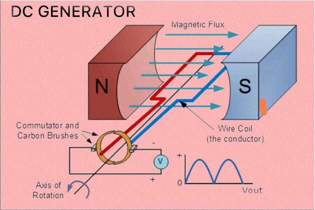
When a conductor moves in a magnetic field or experiences a changing magnetic field, an electromotive force (EMF) is induced in the conductor. This phenomenon, known as electromagnetic induction, forms the basis for the functioning of DC generators.

The EMF equation of a DC generator is derived from Faraday’s law of electromagnetic induction, which states that the induced EMF is proportional to the rate of change of magnetic flux passing through a conductor. By applying this principle to a rotating armature coil in a DC generator, we can determine the relationship between the generated voltage and various factors that influence it.
The EMF equation of a DC generator is expressed as below
E = P * Z* Φ*N / (60*A)
where E represents the generated EMF, P is the number of poles, Φ denotes the magnetic flux per pole, Z represents the total number of conductors in the armature, N is the rotational speed of the generator, and A is the number of parallel paths in the armature windings.
Derivation of EMF Equation of a DC Generator
To derive the EMF equation of a DC generator, we can start with Faraday’s law of electromagnetic induction, which states that the induced EMF in a conductor is proportional to the rate of change of magnetic flux passing through it.
The expression for the flux cut by a single conductor in one revolution of the armature is given by:
Flux cut by one conductor = (1)

The time taken for one complete rotation is expressed as: (2)

Thus, the average induced electromotive force (e.m.f) in one conductor can be determined as: (3)

Substituting the value of t from Equation (2) into Equation (3) results in: (4)

The number of series-connected conductors in each parallel route is denoted as Z/A. Consequently, the average induced e.m.f across each parallel route or armature terminal is given by: (5)

Alternatively, expressing the speed in revolutions per second n=N/60, and considering the number of poles and conductors per parallel route Z/A) as constants, Equation (5) can be represented as:

Here, K is a constant defined by K=PZ/A. Thus, the average induced e.m.f equation can be expressed as:

Where K1 is another constant, and the induced e.m.f equation is further simplified as:

The angular velocity in radians per second is denoted as ω=2πN/60. Consequently, the induced e.m.f is directly related to the speed and flux per pole. The polarity of the induced e.m.f is determined by the magnetic field direction and the rotational direction.
The polarity changes if either of these is reversed, but if both are reversed, the polarity remains unchanged. This generated e.m.f is a fundamental occurrence in all DC machines, whether functioning as generators or motors.
For a DC machine used as a generator or EMF equation of a DC generator is given by:

For a DC machine used as a motor, the induced e.m.f is given by:

The induced e.m.f in a motor is commonly referred to as “back e.m.f” Eb) since it opposes the direction of the supply voltage.
This equation demonstrates that the generated voltage of a DC generator is affected by the number of poles, magnetic flux per pole, rotational speed, total number of conductors, and the number of parallel paths. Understanding the significance of these factors allows for the analysis and optimization of DC generator performance.
The EMF equation of a DC generator serves as a foundation for designing and evaluating electrical systems that utilize DC generators. It is used in applications such as power plants, renewable energy systems, and various industrial processes where precise control and regulation of generated voltage are required.
By manipulating the factors in the EMF equation of a dc generator, engineers and designers can tailor the output voltage of DC generators to meet specific requirements and ensure optimal performance. Overall, the EMF equation provides a fundamental understanding of the relationship between the physical characteristics of a DC generator and its generated voltage.

Rotational Speed (N): The rotational speed of the DC generator is given in revolutions per minute (RPM). The speed at which the armature rotates affects the frequency and magnitude of the generated EMF.
Total Conductors (Z): Z represents the total number of conductors in the armature winding. In a DC generator, the armature windings consist of multiple coils arranged in slots on the armature core. Each coil contributes to the total number of conductors.
Parallel Paths (A): A refers to the number of parallel paths in the armature windings. It represents the number of separate paths that the armature current can flow through. The value of A is usually determined by the design and construction of the armature.
Conclusion
The EMF equation of a DC generator shows that the generated voltage is directly proportional to the product of magnetic flux per pole (Φ), rotational speed (N), and the total number of conductors in the armature (Z). It is inversely proportional to the number of parallel paths (A) and the number of poles (P).
By manipulating these factors, such as by changing the strength of the magnetic field or the rotational speed of the generator, it is possible to control and adjust the output voltage of a DC generator.
Understanding the EMF equation of a DC generator is crucial for analyzing and designing electrical systems that utilize DC generators, such as power plants, renewable energy systems, and various industrial applications.
The EMF equation of a dc generator provides valuable insights into the relationship between the generator’s physical characteristics and its generated voltage. It is widely used in the design, analysis, and optimization of DC generators in various applications, including power plants, renewable energy systems, and industrial processes.
Follow us on LinkedIn”Electrical Insights” to get the latest updates in Electrical Engineering. You can also Follow us LinkedIn to see our latest posts.
Frequently Asked Questions
What is the EMF equation of a DC generator?
The EMF equation of a DC generator is given by E = P * Φ * Z / (60 * N * A), where E represents the generated electromotive force (EMF), P is the number of poles, Φ is the magnetic flux per pole, Z is the total number of conductors in the armature, N is the rotational speed of the generator, and A is the number of parallel paths in the armature windings.
What does the EMF equation of a DC generator represent?
The EMF equation represents the relationship between the generated voltage (EMF) of a DC generator and various factors that influence it. It provides insights into how the number of poles, magnetic flux, rotational speed, total conductors, and parallel paths impact the output voltage.
How is the EMF equation derived?
The EMF equation is derived from Faraday’s law of electromagnetic induction, which states that the induced EMF is proportional to the rate of change of magnetic flux. By applying this principle to a rotating armature coil in a DC generator and considering the number of poles, magnetic flux, rotational speed, conductors, and parallel paths, the equation is derived.
What is the significance of the EMF equation of a DC generator?
The EMF equation is essential for analyzing, designing, and optimizing DC generator performance. It helps engineers understand how changing parameters like magnetic flux, rotational speed, and conductor count affect the generated voltage. The equation enables precise control and regulation of the output voltage in applications such as power plants, renewable energy systems, and industrial processes.
Can the EMF equation be used to control the generated voltage of a DC generator?
Yes, the EMF equation provides insight into the factors that affect the generated voltage. By manipulating these factors, such as adjusting the magnetic flux or rotational speed, it is possible to control and regulate the output voltage of a DC generator.
Are there any limitations or assumptions associated with the EMF equation of a DC generator?
The EMF equation assumes ideal operating conditions and neglects factors like losses, armature reaction, and saturation effects. Real-world generators may deviate from the ideal behavior described by the equation. To account for these factors, additional considerations and empirical data may be necessary in practical applications.
How is the EMF equation applied in the design of DC generators?
The EMF equation is used as a design tool to determine the appropriate number of poles, magnetic field strength, and armature characteristics for a DC generator based on desired voltage requirements. It helps engineers optimize generator performance and ensure that it meets specific application needs.


