A Quick Guide to Oscillator Circuit Diagram and Working
Table of Contents
Introduction
The oscillator is a circuit that generates repeating AC signals from DC. In this article, we will see how an oscillator circuit diagram works. These circuits produce oscillations with the desired frequency and required amplitude depending upon the circuit elements and design. These circuits may involve the amplifier circuit to amplify the signal according to the requirement of oscillations.
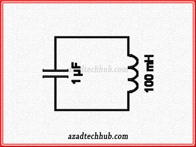
To understand the functionality of the oscillator, we need to understand the behavior of the inductor and capacitor in any circuit. When we connect the inductor and capacitor in any circuit, they tend to store the energy in the form of electromagnetic and electrostatic fields. In the case of turning off the input supply, they provide the stored energy at the output. Let’s have a look at below inductor and capacitor combinations, before discussing the functionality of an oscillator circuit.
Oscillator Circuit Diagram

In the above circuit, we can see the inductor and capacitor are in parallel. When the supply turns on, the capacitor charges, and when the supply turns zero, the capacitor charges the inductor until it discharges completely. Then again the inductor starts supplying the current in the circuit, which is how oscillations generate in any circuit.
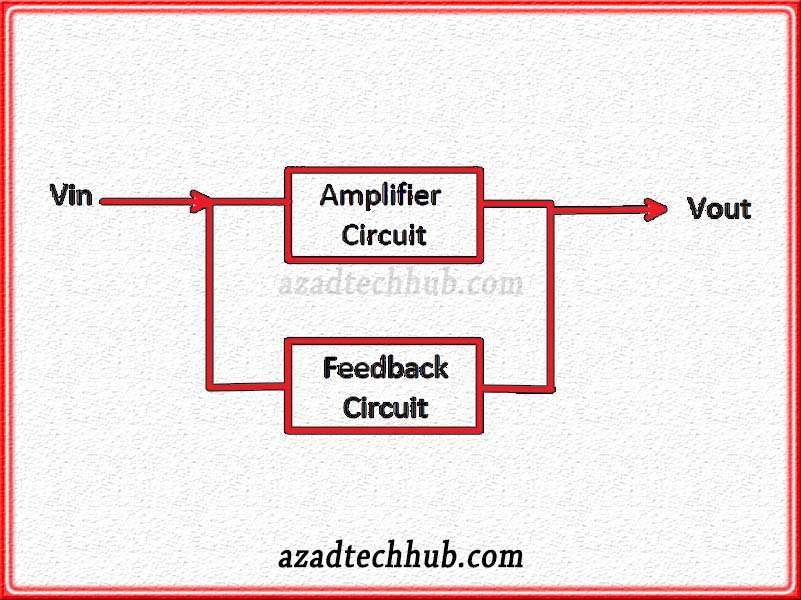
oscillator Circuit Block Diagram
These oscillations fade out with the passage of time due to the losses because of the resistance of the circuit. So, to keep the amplitude of the oscillations high we need an amplifier in the circuit with some feedback mechanism. Whenever the amplitude of the oscillations becomes low, this amplifier circuit must enhance the oscillations and the reverse will happen with the increasing amplitude of oscillations. Let’s have a look at below oscillator circuit diagram in blocks.

“Vin” is the output from the oscillator circuit and “Vout” is the output of the amplifier circuit. In this block diagram, the feedback plays the role to maintain the amplitude of oscillations in the circuit.
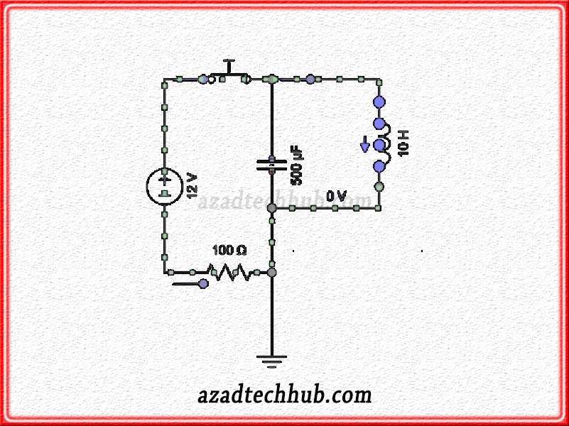
Oscillator Circuit Diagram in Closed Loop
As per our above discussion, we know how an oscillator circuit works and how the oscillations in any circuit generate. Let’s move further and discuss an oscillator circuit working in a closed circuit. Have a look at the below oscillator circuit diagram.

In the above circuit, we have a combination of inductor and capacitor in circuit and when we turn on the circuit or close the switch, current starts flowing through the inductor, and the capacitor charges with the supply. We can see the current direction through the inductor as well. When the switch opens or disconnects, the charged capacitor releases the stored energy in the circuit and charges the inductor and the process starts with repetition generating oscillations in the circuit. We can check below after the disconnect of a switch in oscillator circuit diagram.

As we can see in the above figure that when we disconnect the switch the charged capacitor starts supplying current in the circuit and charges the inductor. This is how the oscillations generate in the circuit and that’s why we call these types of circuits oscillator circuits. Read about amplifier circuits.
Oscillator Integrated Circuits
Here are a few examples of popular oscillator ICs:
555 Timer IC: The NE555 or LM555 is a widely used timer IC that can be configured as an astable or monostable oscillator. It is versatile and can generate square, pulse, or timing signals.
74HC04 Hex Inverter IC: The 74HC04 is a popular hex inverter IC that can be used as an oscillator by connecting feedback components. It can generate square waves and is commonly used in simple oscillator circuits.
74HC14 Hex Schmitt Trigger IC: The 74HC14 is a hex Schmitt trigger IC that can be utilized as an oscillator by configuring it with suitable components. It can generate square waves with improved noise immunity.
XR2206 Function Generator IC: The XR2206 is a specialized IC designed for generating a variety of waveforms, including sine, triangle, and square waves. It can operate as an oscillator to produce precise frequency signals.
CD4046 Phase-Locked Loop (PLL) IC: The CD4046 is a PLL IC that can function as an oscillator when used in the voltage-controlled oscillator (VCO) mode. It is commonly used for frequency synthesis and clock generation applications.
These are just a few examples of oscillator ICs, and there are many more options available depending on your specific requirements and application needs.
Follow us on LinkedIn”Electrical Insights” to get the latest updates in Electrical Engineering. You can also Follow us LinkedIn to see our latest posts.
Worth Read Posts
- OBD2 Pinout
- Throttle Position Sensor
- LR44 Battery
- CR123 Battery
- Lithium Ion Batteries
- Methods of Electrical Earthing
- Electrical Earthing Important Types
- Plant Factor, Plant Capacity Factor, and Load Factor
- Buck Converter Interview Questions
- DC DC Converter Interview Questions


