High Voltage Transformer Testing Procedure
High voltage transformers are at the heart of every power system. They step up and step down voltages to keep energy flowing safely and efficiently. Because these machines operate at very high stress levels, testing them is essential before commissioning and throughout their service life. A proper high voltage transformer testing procedure ensures reliability, safety, and compliance with international standards.
Transformers can fail due to insulation breakdown, winding faults, oil contamination, or mechanical stresses. Testing allows engineers to detect hidden issues early and avoid costly downtime. Every test is designed to check a different characteristic of the transformer such as insulation strength, winding resistance, or dielectric properties. By following a systematic approach, we can be confident that the transformer will work reliably under load.
Table of Contents
Table of Contents
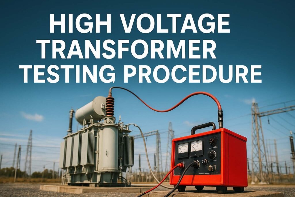
A high voltage transformer testing procedure is not just a checklist. It is a structured process that covers visual inspection, electrical measurements, dielectric testing, and functional checks. Each test provides specific data that engineers can analyze to confirm that the transformer meets design and safety requirements.
Key Takeaways
- High voltage transformer testing verifies electrical, mechanical, and insulation integrity.
- Testing is carried out during factory acceptance, installation, and regular maintenance.
- Common tests include insulation resistance, turns ratio, power factor, and high voltage withstand.
- Following international standards (IEC, IEEE, ANSI) ensures consistent and reliable results.
- Regular testing prevents catastrophic failures and extends transformer life.
Know more about IEC Standard for DGA Analysis – Complete Technical Guide
Importance of High Voltage Transformer Testing Procedure
Transformers operate under heavy electrical and thermal stress. Without proper testing, the risk of failure increases significantly. A breakdown can lead to equipment damage, long outages, and even safety hazards. By conducting routine tests, operators can:
- Verify compliance with specifications.
- Detect early signs of insulation deterioration.
- Measure winding condition and mechanical stability.
- Check the dielectric strength of transformer oil and solid insulation.
- Ensure safe operation before energizing the system.
Standard Guidelines for High Voltage Transformer Testing Procedure
The high voltage transformer testing procedure is usually performed according to IEC 60076, IEEE C57, and ANSI standards. These guidelines define test types, methods, and acceptable limits. The tests are broadly divided into:
- Routine Tests: Performed on every unit before delivery.
- Type Tests: Conducted on a few units to verify design.
- Special Tests: Requested by customers for specific applications.
Know more about Transformer Protection Schemes: Types and Application Guide
Below is a comparison of major test categories.
| Test Category | Examples of Tests | Purpose |
|---|---|---|
| Routine Tests | Winding resistance, ratio, insulation resistance, dielectric tests | Confirm basic performance |
| Type Tests | Short-circuit withstand, temperature rise, impulse test | Validate design and thermal behavior |
| Special Tests | Partial discharge, frequency response, dissolved gas analysis | Evaluate unique performance aspects |
Step-by-Step High Voltage Transformer Testing Procedure
Visual and Physical Inspection
Before electrical testing, engineers must carry out a detailed visual inspection. The aim is to check for oil leaks, bushing damage, loose connections, or corrosion. Nameplates and ratings are verified. Oil levels, silica gel condition, and mechanical accessories are checked. This step is simple but critical in detecting obvious defects.
Measurement of Winding Resistance
Winding resistance reveals the condition of conductors, joints, and contacts. A micro-ohmmeter is used to inject DC current and measure resistance values. High differences between phases may indicate loose connections or shorted turns. Accurate resistance data also helps in future maintenance comparisons.
Know more about Differential Protection of Transformer: Working, Settings & Calculation
Transformer Turns Ratio (TTR) Test
The turns ratio test confirms that the primary and secondary windings maintain the correct voltage transformation ratio. A TTR meter applies a low voltage and measures induced voltage on the secondary side. Deviations from the nameplate value may indicate shorted turns or insulation issues.
Insulation Resistance Test
The insulation resistance test is performed using a megohmmeter (commonly 500V, 1000V, or 5000V depending on rating). It checks the condition of insulation between windings and between winding to ground. Higher resistance indicates good insulation, while lower values point to contamination or moisture ingress.
Dielectric Power Factor and Dissipation Factor Test
Also known as the tan-delta test, this procedure evaluates insulation quality. The dielectric power factor test applies an AC voltage and measures leakage current. A high dissipation factor shows aging insulation or contamination. This test is crucial in preventive maintenance programs.
High Voltage Withstand (Applied Voltage Test)
This is one of the most important steps in the high voltage transformer testing procedure. A high test voltage is applied between windings and ground to confirm insulation strength. The voltage is maintained for one minute. The transformer passes the test if no breakdown or flashover occurs.
Induced Overvoltage Test
Here, a voltage higher than the rated value is applied to the secondary winding. The purpose is to check insulation strength under overvoltage conditions. Since the test uses high frequency (around twice the rated frequency), it stresses the insulation effectively without causing overheating.
Know more about Overcurrent Protection of Transformer: A Complete Technical Guide
Partial Discharge Test
Partial discharge occurs when small electric sparks form inside insulation voids. These discharges accelerate aging and can lead to failure. The partial discharge test measures these signals under high voltage stress. A low PD value indicates healthy insulation, while high readings demand corrective actions.
Transformer Oil Testing
For oil-filled transformers, dielectric oil plays a vital role in insulation and cooling. Oil samples are tested for breakdown voltage, moisture content, acidity, and dissolved gases. Dissolved Gas Analysis (DGA) is particularly important because it identifies early faults like arcing, overheating, or corona.
| Oil Test | Parameter Checked | Acceptable Value |
|---|---|---|
| Breakdown Voltage | Dielectric strength | > 30 kV |
| Moisture Content | Water in oil (ppm) | < 20 ppm (new oil) |
| Acidity | Neutralization value | < 0.1 mg KOH/g |
| DGA | Fault gases (H₂, CO, CH₄, C₂H₂) | Within IEC limits |
Temperature Rise Test
This test measures the thermal performance of the transformer under full load. The unit is energized at rated current until steady-state temperature is reached. Winding resistance is recorded to calculate temperature rise. This test ensures the transformer can handle its load without overheating.
Impulse Test
Impulse testing simulates lightning strikes and switching surges. The transformer is subjected to high-voltage impulses of specific waveforms. Its ability to withstand these surges without insulation breakdown is confirmed. This is a critical design verification test.
Additional Diagnostic Tests in High Voltage Transformer Testing Procedure
Some modern techniques provide deeper insight into transformer condition.
- Sweep Frequency Response Analysis (SFRA) checks mechanical displacement of windings.
- Frequency Domain Spectroscopy (FDS) assesses moisture in insulation.
- Polarization Index (PI) test measures insulation resistance over time.
- Infrared Thermography identifies hot spots in bushings and windings.
These advanced tests are often performed as part of predictive maintenance to extend transformer life.
Know more about Polarization Index (PI): Importance, Calculation, and Testing Procedures
Interpretation of Test Results
Raw test values are compared against standards and historical data. For example, a drop in insulation resistance compared to previous years indicates moisture ingress. High winding resistance imbalance suggests loose connections. Engineers must not only perform tests but also analyze trends. Predictive analysis prevents future breakdowns.
Safety Precautions During High Voltage Transformer Testing Procedure
Testing involves hazardous voltages and currents. Strict safety protocols are mandatory.
- Only trained personnel should conduct tests.
- Test areas must be barricaded and grounded.
- Equipment must be properly rated and calibrated.
- Operators must wear insulated gloves, boots, and protective gear.
- Emergency procedures must be in place before starting.
Conclusion
The high voltage transformer testing procedure is a systematic approach that ensures safety, reliability, and efficiency of power systems. From visual checks to advanced diagnostic techniques, every step contributes to a complete understanding of transformer health. Following international standards like IEC 60076 or IEEE C57 guarantees accuracy and consistency.
Know more about Top 15 Power Transformer Manufacturers in the World
Regular testing not only prevents unexpected failures but also extends the life of the transformer. With electricity demand increasing worldwide, reliable transformers are the backbone of modern power networks. A well-executed testing program ensures that these critical machines operate safely and deliver uninterrupted service for decades.
Follow Us on Social:
Subscribe our Newsletter on Electrical Insights for latest updates from Electrical Engineering Hub
#HighVoltageTransformerTesting, #TransformerTesting, #ElectricalTesting, #PowerTransformer, #HighVoltageTesting, #TransformerMaintenance, #TransformerProcedure, #ElectricalEngineering, #TransformerProtection, #SubstationTesting, #EnergyInfrastructure, #TestingStandards, #TransformerReliability, #ElectricalSafety, #TransformerInspection


Wow! This could be one particular of the most useful blogs We’ve ever arrive across on this subject. Actually Wonderful. I am also a specialist in this topic therefore I can understand your effort.