What is Automatic Power Factor Correction Using Capacitor Bank?
Automatic power factor correction is one of the most essential techniques used in electrical systems today. It helps improve efficiency, reduces energy losses, and prevents penalties from utility companies. In industries and commercial setups where large motors and inductive loads are present, the power factor tends to drop. This leads to wasted energy, higher bills, and unnecessary strain on the electrical infrastructure. Automatic power factor correction using capacitor banks provides an intelligent and reliable solution.
Table of Contents
Table of Contents
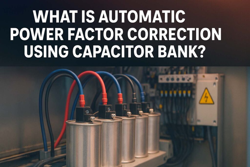
Before we go into technical details, if you want to calculate the exact capacitor size needed for your system, you can use this free tool: Power Factor Correction Calculator. It allows you to size capacitors accurately and achieve the best efficiency in your network.
Power factor is simply the ratio of real power (kW) to apparent power (kVA). When the power factor is low, more current flows in the system than actually needed to perform useful work. This extra current increases copper losses, causes voltage drops, and may even require oversized transformers or cables. Improving power factor means reducing these losses and running the system efficiently. Automatic systems take this further by ensuring correction happens dynamically, without human intervention.
Key Takeaways:
- Automatic power factor correction ensures continuous monitoring and adjustment of power factor.
- Capacitor banks are the most common and cost-effective solution for correction.
- It helps reduce electricity bills, prevents penalties, and enhances system life.
Automatic power factor correction works by using a capacitor bank connected to the power distribution system. Capacitors generate reactive power that offsets the lagging reactive power produced by inductive loads like motors, welding machines, and transformers. The challenge with manual correction is that load conditions vary throughout the day. A fixed capacitor may either undercompensate or overcompensate depending on the load. That is why automatic systems are preferred.
In an automatic system, power factor is continuously measured by a power factor relay or microprocessor-based controller. Whenever the power factor drops below a preset value (say 0.95), the relay automatically switches on a required number of capacitor steps from the capacitor bank. Once the load reduces and power factor improves, the controller switches off unnecessary capacitors. This ensures that power factor always remains close to unity, without any manual adjustment.
Use our online tool for free here Power Factor Correction Capacitor Calculator
How Automatic Power Factor Correction Works
The main components of an automatic power factor correction (APFC) system are:
- Capacitor Bank – Provides the reactive power compensation.
- APFC Relay/Controller – Continuously monitors power factor and decides when to switch capacitors in or out.
- Switching Devices (Contactors or Thyristors) – Physically connect or disconnect capacitors based on the controller’s command.
- Protection Devices – Include fuses, circuit breakers, and discharge resistors for safety.
When the controller detects a lagging power factor, it engages one or more capacitor stages. Each stage is sized for a specific kvar rating, and multiple stages allow fine adjustment of reactive power. In modern systems, contactor-based switching is common in small and medium industries, while thyristor-based switching is used in sensitive systems where fast response is needed.
For example, a textile factory with variable loads from weaving machines may experience a power factor drop from 0.95 to 0.78 during peak operation. An APFC system senses this drop and automatically connects enough capacitor stages to restore the power factor close to 0.98. This happens within seconds and without operator intervention.
Benefits of Automatic Power Factor Correction Using Capacitor Bank
Automatic power factor correction offers a wide range of technical and financial benefits. The most important ones are:
Reduced Electricity Bills: Many utilities impose penalties when the power factor drops below 0.9 or 0.95. Automatic correction eliminates this risk.
Improved Energy Efficiency: By reducing reactive power flow, copper losses and heating in conductors are minimized.
Better Voltage Regulation: Capacitors help maintain voltage levels, improving the performance of motors and other sensitive equipment.
Extended Equipment Life: Lower current flow reduces heating stress on transformers, cables, and switchgear.
Automated Operation: No need for manual intervention, especially in systems with highly variable loads.
Fast Return on Investment: The cost of an APFC system is usually recovered within one to two years due to savings on electricity bills.
Know more about MCC Panel Design Guide – IEC Standards, Wiring Diagram, Cost, and Sizing Calculations (Excel Template)
Comparison Between Manual and Automatic Power Factor Correction
| Feature | Manual Power Factor Correction | Automatic Power Factor Correction |
|---|---|---|
| Adjustment | Fixed capacitor, needs manual switching | Automatic relay switches capacitor stages |
| Accuracy | Poor under variable load | Maintains stable power factor |
| Cost | Lower initial cost | Higher initial but quick payback |
| Maintenance | Low | Moderate |
| Applications | Small loads, stable systems | Industries, commercial buildings, variable loads |
This table clearly shows why industries and commercial buildings prefer automatic power factor correction systems despite their slightly higher cost. The accuracy, automation, and savings they provide make them far superior in the long run.
Technical Insights into Capacitor Bank Design
Capacitor banks are designed based on the kvar requirement of the load. The formula used is:
Q (kvar) = P (kW) × (tan φ1 – tan φ2)
Where:
- P = Active power in kW
- φ1 = Angle corresponding to initial power factor
- φ2 = Angle corresponding to desired power factor
For example, if a 500 kW system has a power factor of 0.75 and we want to improve it to 0.95, the required kvar can be calculated. This calculation is typically automated in modern software and can also be done easily with a tool like the Power Factor Correction Calculator.
Capacitor banks are usually arranged in steps of 5, 10, 20, or 50 kvar. This stepwise arrangement allows the controller to add or remove capacitors as needed. For high-voltage systems, capacitor banks are often installed with reactors to avoid resonance and harmonic amplification.
Know more about Off-Grid Solar System Design Guide for Remote Areas
Challenges in Automatic Power Factor Correction
While automatic power factor correction is highly beneficial, there are certain challenges that engineers need to consider:
- Harmonics: Non-linear loads like variable frequency drives generate harmonics. These harmonics can cause overheating in capacitor banks if not filtered.
- Overcompensation: Adding too much capacitance can result in a leading power factor, which is also undesirable.
- Switching Transients: Rapid capacitor switching may cause voltage transients in sensitive networks. Thyristor-based systems help reduce this.
- Maintenance: Capacitors and contactors require periodic inspection and testing to ensure reliable operation.
These challenges can be overcome by proper system design, harmonic analysis, and using detuned reactors where necessary.
Know more about Short Circuit Calculation Methods: IEC vs ANSI
Applications of Automatic Power Factor Correction
Automatic power factor correction systems are widely used in:
- Industrial plants with heavy motor loads
- Commercial complexes and shopping malls
- Hospitals and data centers with continuous power demand
- Textile, cement, steel, and chemical industries
- Renewable energy systems where inverter-based loads cause poor power factor
Their application is not limited to large industries. Even medium-scale industries can benefit greatly, especially in regions where utilities impose strict power factor penalties.
Know more about Transformer Cooling Methods: ONAN, ONAF, OFAF & More
Conclusion
Automatic power factor correction using capacitor banks is an efficient, reliable, and cost-effective way to maintain high power factor in electrical systems. It eliminates penalties, reduces losses, and improves the overall life of electrical equipment. For industries with variable loads, it is not just an option but a necessity. The technology behind automatic systems ensures that reactive power is always balanced, regardless of load fluctuations.
If you are planning to design or improve your system, make sure to calculate your capacitor bank requirements accurately. You can do this using the Power Factor Correction Calculator, which provides quick and precise results for engineers and plant managers.
Follow Us on Social:
Subscribe our Newsletter on Electrical Insights for latest updates from Electrical Engineering Hub
#AutomaticPowerFactorCorrection, #PowerFactorCorrection, #CapacitorBank, #ElectricalEngineering, #EnergyEfficiency, #IndustrialPower, #PowerSystem, #ElectricalDesign, #SmartGrid, #PowerQuality, #EnergySavings, #ReactivePower, #CapacitorBankDesign, #ElectricalMaintenance, #IECStandards

